Motivation
For the Rundbuntplasma I wanted that the main power supply (a big 20A/5V supply) could be hard disconnected (aka operating the main power switch in our hacker space) from mains and the Raspberry will still shutdown nicely automatically. The idea is to buffer the 5V for the Raspberry using two big Supercapacitors (EDLCs) with 50F each from Nesscap. The circuit was designed to be as simple as possible, the drawback is that the capacity is not used efficiently and has only enough time for a proper short shutdown (about 30 seconds). Another drawback is that the power supply comes up slowly at startup (takes about 10 seconds before Raspberry starts booting) and also powers the Raspberry for quite a long time after the shutdown so the system must be unplugged for about 10min before it will boot up again. But there main advantage over batteries is the lifetime of supercaapacitors: They can be charged and discharged completely a few 100.000 times and are quick to charge - after ~2min they carry enough charge for proper shutdown.
So no worry of proper shutdown anymore - just unplug it or operate the main power switch and the Raspberry will detect it and shutdowns nicely while the supercapacitors provide the power for this time.
Circuit
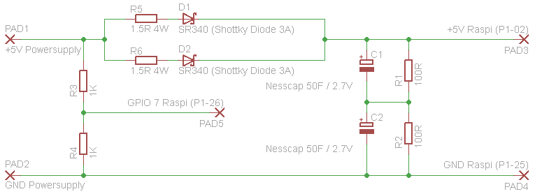
The powersupply goes in at the left side, the diodes prevent that current will be flowing back to the power supply and the resistors R5/R6 limit the current at startup rushing into the Supercaps (otherwise the diodes or the power supply might die). The diodes should be schottky-diodes with a high current and low V_foreward rating, so many types will do. SR340 was choosen only because it has been found in the drawer. R5/R6 could also anything between 0.5R and 2R but high wattage types should be choosen - especially at startup they might get hot.
The supercaps C1/C2 must be connected in series and the resistors R1/R2 are used that the voltage over the caps will be distributed evenly (balancing), otherwise the caps may degrade quickly. The resistors also discharge the caps slowly when the circuit is not powered (but within a quite long time) that is also good to lenghten the live of the supercaps.
With R3/R4 the input voltage of 5V is simply divided by half and connected to GPIO pin 7. When the main power supply fails the level at this pin quickly drops to a low-level, otherwise the Raspi will detect a high-level. A simple shell-script using the "gpio" command is polling every second the state of this pin and trigger a shutdown if the level goes to zero.
Warning
The EDLCs used from Nesscap are specified with a maximum ESR of 16mΩ - charged at 2.5V this will result in a minimum discharge current of >150A in case of short circuit. So don't short circuit them when they are charged, otherwise something might burn or became welded...
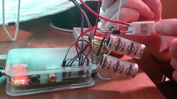
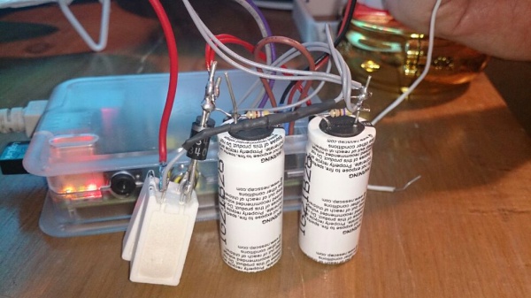
Pictures from quick'n'dirty hack
Result
It works pretty well but those big caps are expensive if you have to buy them. It could be done much better and with much smaller supercaps if a step-up-converter or even better a step-up-and-down-converter is used to generate the 5V. The Raspberry uses a very unefficient linear regulator for 3.3V by default - by changing that to a switched-one the holdup time can be increased also.
As most things on the Raspberry will operate on 3.3V supply, it does not matter much that the 5V is just 4.5V or even lower as it will be the case with this very simple circuit. But beware, devices on USB port (especially WLAN adapters) may really want nearly full 5V for proper operation...


