Zen Toolworks CNC Fräse: Unterschied zwischen den Versionen
Aus Hackerspace Ffm
Axl (Diskussion | Beiträge) K (→Links & more infos) |
Axl (Diskussion | Beiträge) (→Info zur Zen Toolworks 1212) |
||
| (66 dazwischenliegende Versionen von 2 Benutzern werden nicht angezeigt) | |||
| Zeile 1: | Zeile 1: | ||
[[Datei:Laermschutz.png|200px|right|thumb|CNC Fräsen - es wird laut]] | [[Datei:Laermschutz.png|200px|right|thumb|CNC Fräsen - es wird laut]] | ||
| − | + | = Info zur Zen Toolworks 1212 = | |
* '''Daniels Leihgabe an den Hackerspace Ffm''' | * '''Daniels Leihgabe an den Hackerspace Ffm''' | ||
* Typ Zen Toolworks 12x12 Inch | * Typ Zen Toolworks 12x12 Inch | ||
| Zeile 16: | Zeile 16: | ||
Datei:Foto1519.jpg|Zen Toolworks CNC | Datei:Foto1519.jpg|Zen Toolworks CNC | ||
Datei:Foto1521.jpg|CNC Elektronik | Datei:Foto1521.jpg|CNC Elektronik | ||
| + | Datei:CNC 2013-11-04 IMAG0722.jpg|Doku - Verkabelung (07-2013) | ||
| + | Datei:CNC 2013-11-04 IMAG1315.jpg|Doku - Verkabelung (11-2013) | ||
| + | Datei:CNC 2013-11-04 IMAG1316.jpg|Doku - Setup (11-2013) | ||
</gallery> | </gallery> | ||
| − | + | = CNC Revival project = | |
| − | + | == Ziele == | |
* Dezember 2011 - Februar 2012 | * Dezember 2011 - Februar 2012 | ||
** Fräse betriebsbereit und getestet | ** Fräse betriebsbereit und getestet | ||
| Zeile 33: | Zeile 36: | ||
** Staub | ** Staub | ||
| − | + | == Hardware, Software == | |
* Anschluß zunächst über Parallel-Port / Centronics | * Anschluß zunächst über Parallel-Port / Centronics | ||
** geplant: USB Interface | ** geplant: USB Interface | ||
| Zeile 48: | Zeile 51: | ||
** optisch / mechanisch? | ** optisch / mechanisch? | ||
| − | + | == Tests am 10.12.2011 == | |
<gallery perrow=5> | <gallery perrow=5> | ||
Datei:2011-12-10 22.46.00.jpg|Setup Ubuntu und EMC | Datei:2011-12-10 22.46.00.jpg|Setup Ubuntu und EMC | ||
| Zeile 57: | Zeile 60: | ||
</gallery> | </gallery> | ||
| − | + | == Joypad Steuerung == | |
* 14.12.2011 | * 14.12.2011 | ||
* Konfiguration eines ''Logitech Logitech Dual Action'' Joypad an EMC zu Steuerung der X, Y, Z Achsen | * Konfiguration eines ''Logitech Logitech Dual Action'' Joypad an EMC zu Steuerung der X, Y, Z Achsen | ||
| Zeile 64: | Zeile 67: | ||
| − | + | = Production mode = | |
| − | + | == Inkscape g-code Export == | |
* 14.12.2011 | * 14.12.2011 | ||
* Inkscape unter Ubuntu | * Inkscape unter Ubuntu | ||
| Zeile 80: | Zeile 83: | ||
</gallery> | </gallery> | ||
| − | + | == Bohren der LED Platinen für das [[Buntich|Buntich Projekt]] == | |
* Massen-Bohrung für das [[Buntich|Buntich Projekt]] | * Massen-Bohrung für das [[Buntich|Buntich Projekt]] | ||
* je 4 Bohrungen je LED Platine | * je 4 Bohrungen je LED Platine | ||
| Zeile 124: | Zeile 127: | ||
| − | + | == Platinen fräsen und bohren == | |
* CAD für PCB Entwurf: Win Layout von Abacom | * CAD für PCB Entwurf: Win Layout von Abacom | ||
| Zeile 143: | Zeile 146: | ||
<br/> | <br/> | ||
| − | + | == XYZ Blinkenlights for CNC Mills == | |
[[Datei:XYZ Blinkenlights 001.png|320px|none|thumb|Screenshot Processing]] | [[Datei:XYZ Blinkenlights 001.png|320px|none|thumb|Screenshot Processing]] | ||
| Zeile 151: | Zeile 154: | ||
<br/> | <br/> | ||
| − | + | == Drawbot Logo == | |
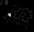
[[Datei:Drawbot g-code B.png|320px|none|thumb|DRAWBOT Logo]] | [[Datei:Drawbot g-code B.png|320px|none|thumb|DRAWBOT Logo]] | ||
* Ausgabe des Drawbot Fonts per Processing in g-Code | * Ausgabe des Drawbot Fonts per Processing in g-Code | ||
| Zeile 165: | Zeile 168: | ||
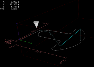
| − | + | == Kissen / Gußform Test == | |
[[Datei:Bildschirmfoto-Kissen ngc.png|320px|none|thumb|Kissen-Form in EMC]] | [[Datei:Bildschirmfoto-Kissen ngc.png|320px|none|thumb|Kissen-Form in EMC]] | ||
* Fräsen einer Kissen-Form in Schaustoff | * Fräsen einer Kissen-Form in Schaustoff | ||
| Zeile 187: | Zeile 190: | ||
| − | + | == Drawbot Gondel-Teil - OpenSCAD == | |
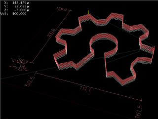
[[Datei:PenDisc V 003 combined paths 0005 filter 001.png|320px|none|thumb|EMC Screen]] | [[Datei:PenDisc V 003 combined paths 0005 filter 001.png|320px|none|thumb|EMC Screen]] | ||
* Fräsen eines in OpenSCAD konstruierten Teils aus Kunststoff | * Fräsen eines in OpenSCAD konstruierten Teils aus Kunststoff | ||
| Zeile 193: | Zeile 196: | ||
* Konvertierung in g-Code mit Inkscape | * Konvertierung in g-Code mit Inkscape | ||
| − | + | === OpenSCAD 3D zu 2D Konvertierung === | |
<nowiki>[...] | <nowiki>[...] | ||
// projection(cut=true) for DXF extrude | // projection(cut=true) for DXF extrude | ||
| Zeile 202: | Zeile 205: | ||
} // projection(cut=true) for DXF extrude</nowiki> | } // projection(cut=true) for DXF extrude</nowiki> | ||
| − | + | === Probleme === | |
* DXF Import | * DXF Import | ||
** Pfad wird beim Export nicht zusammengeführt | ** Pfad wird beim Export nicht zusammengeführt | ||
| Zeile 222: | Zeile 225: | ||
| − | + | == [[Buntich|Buntich]] Aussparungen für Kabelkanäle == | |
| − | + | === Buntich Datenleitungen === | |
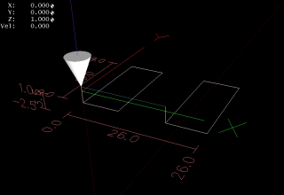
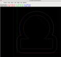
[[Datei:Buntich Bohrung Bildschirmfoto.png|320px|none|thumb|EMC Screen]] | [[Datei:Buntich Bohrung Bildschirmfoto.png|320px|none|thumb|EMC Screen]] | ||
* Fräsen rechteckiger Aussparungen in die [[Buntich|Buntich]] Kabelkanäle | * Fräsen rechteckiger Aussparungen in die [[Buntich|Buntich]] Kabelkanäle | ||
| Zeile 237: | Zeile 240: | ||
</gallery> | </gallery> | ||
| − | + | === Buntich Datenleitungen - g-Code === | |
<nowiki>% | <nowiki>% | ||
(Bohren der Kabelkanäle für das Buntich Projekt) | (Bohren der Kabelkanäle für das Buntich Projekt) | ||
| Zeile 271: | Zeile 274: | ||
| − | + | === Buntich 4mm Stecker === | |
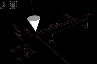
[[Datei:Buntich 4mm Löcher Bildschirmfoto.png|320px|none|thumb|EMC Screen]] | [[Datei:Buntich 4mm Löcher Bildschirmfoto.png|320px|none|thumb|EMC Screen]] | ||
| Zeile 278: | Zeile 281: | ||
| − | + | === Buntich Kabeldurchführung === | |
[[Datei:Buntich Kabeldurchführung Bildschirmfoto.png|320px|none|thumb|EMC Screen]] | [[Datei:Buntich Kabeldurchführung Bildschirmfoto.png|320px|none|thumb|EMC Screen]] | ||
| Zeile 292: | Zeile 295: | ||
</gallery> | </gallery> | ||
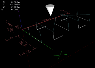
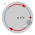
| − | == | + | == g-Codes G02 & G03 - Bögen == |
| − | * [http:// | + | [[Datei:Mill tracer 005 Bildschirmfoto.png|320px|none|thumb|EMC Screen]] |
| − | * [http://groups.google.com/group/zen-toolworks/topics?hl=en&start=50&sa=N Zen Toolworks Google group] | + | * [http://www.cnccookbook.com/CCCNCGCodeArcsG02G03.htm g-Code infos] |
| − | * [http://wiki.zentoolworks.com/index.php/Main_Page ZEN Toolworks Wiki] | + | * G02 - clockwise arc |
| + | * G03 - conter-clockwise arc | ||
| + | * Parameter I, J und K - Bogen-Zentrum X, Y und Z | ||
| + | * Test mit Processing: Bohrungen, Langlöcher, Rechtecke mit Radius fräsen | ||
| + | |||
| + | <gallery caption="g-Codes G02 & G03 - Bögen"> | ||
| + | Datei:Mill tracer hole sketch.png|Bohrung | ||
| + | Datei:Mill tracer rect sketch.png|Rechtecke | ||
| + | Datei:Mill tracer IMG 1677-1280.jpg|Tests fräsen | ||
| + | Datei:Mill tracer IMG 1679-1280.jpg|Tests fräsen | ||
| + | </gallery> | ||
| + | |||
| + | === cnc_path() & Egg-Bot Prototyp === | ||
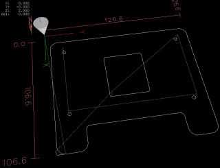
| + | [[Datei:Eggbot prototyp-2012-01-29 (2) Bildschirmfoto.png|320px|none|thumb|EMC Screen]] | ||
| + | * Processing-Funktion cnc_path() erlaubt das Fräsen nach Pfaden incl. abgerundeter Ecken | ||
| + | * Aktuelle Version: Nur 90° Schritte möglich | ||
| + | * Außen- und Innen-Radien werden individuell berechnet und mit "echten" Bögen (g-Code G02/G03) gefräst | ||
| + | * erste Anwendung: Rahmenteile für den [[Egg-Bot]] Prototyp | ||
| + | |||
| + | <gallery caption="Eggbot Prototyp"> | ||
| + | Datei:Mill tracer path sketch.png|Prinzip der 90° cnc_path() Funktion | ||
| + | Datei:Eggbot prototyp-2012-01-29 (1)-1280.jpg|Prototyp - Stepper NEMA 14 mount | ||
| + | Datei:Eggbot prototyp-2012-01-29 (2)-1280.jpg|Prototyp - Stepper | ||
| + | Datei:Eggbot prototyp-2012-01-29 (4)-1280.jpg|Prototyp - Stepper | ||
| + | Datei:Mill tracer 012 Bildschirmfoto.png|Erweiterung: Stege zum Ausbrechen | ||
| + | Datei:Mill tracer 012 Eggbot CNC split IMG 1694.jpg|Fräsen: Stege zum Ausbrechen | ||
| + | Datei:Eggbot prototyp-2012-01-29 (5)-1280.jpg|Prototyp - gesamt | ||
| + | Datei:Foto2072.jpg|Milling the Egg-Bot | ||
| + | </gallery> | ||
| + | |||
| + | == Tests mit pycam == | ||
| + | [[Datei:Pycam Toolchain Demo.png|320px|none|thumb|Inkscape --> pycam --> EMC2]] | ||
| + | === Installation unter Ubuntu === | ||
| + | http://pycam.sourceforge.net/ | ||
| + | |||
| + | sudo apt-get install python-gtk2 python-opengl python-gtkglext1 python-rsvg python-pyode python-guppy | ||
| + | sudo apt-get install inkscape pstoedit | ||
| + | |||
| + | === Test-Fräsen === | ||
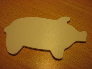
| + | * Beispiel: [http://openclipart.org/detail/2232/johnny_automatic_piggie_sihouette a pig silhouette from a U.S. patent drawing] | ||
| + | [[Datei:Piggie sihouette IMG 1724-1280.jpg|thumbnail]] | ||
| + | |||
| + | <gallery caption="CNC Piggie"> | ||
| + | Datei:Piggie sihouette.png|Piggie Vorlage | ||
| + | Datei:Piggie sihouette IMG 1724-1280.jpg|Kunststoff | ||
| + | Datei:IMG 1730.JPG|Alte Telefonkarte zu Piggie | ||
| + | </gallery> | ||
| + | |||
| + | |||
| + | == Neue Fräser-Aufnahme und Tests 9 mm Multiplex Sperrholz == | ||
| + | * Die neue Fräser-Aufnahme reicht deutlich näher an den Frästisch - Danke, Lötmichel | ||
| + | * Tests mit Version 1 für die Proxxon Bohrmaschine und 9 mm [http://de.wikipedia.org/wiki/Multiplex-Platte Multiplex Sperrholz] | ||
| + | * Version 2 - mit neuem Motor - in Arbeit | ||
| + | |||
| + | <gallery caption="CNC Piggie"> | ||
| + | Datei:IMG 1780.JPG|Neue Fräser-Aufnahme für die Proxxon ... | ||
| + | Datei:IMG 1781.JPG|... im Detail | ||
| + | Datei:Eggbot outer cut 0000 Bildschirmfoto.png|Wood-Cut | ||
| + | Datei:IMG 1782.JPG|Wood-Cut | ||
| + | </gallery> | ||
| + | |||
| + | == Egg-Bot Schild == | ||
| + | * 3-Teiliges Schild für den [[Egg-Bot]]: | ||
| + | ** Unterer Rahmen für Aufnahme des Glas-Teils + LED (g-Code via Processing) | ||
| + | ** Abdeck-Rahmen (g-Code via Processing) | ||
| + | ** Graviertes Glas-Teil (g-Code via InkScape --> pyCAM) | ||
| + | * Font: Century Schoolbook L ([http://en.wikipedia.org/wiki/Century_Type_Family Century Type Family]) | ||
| + | |||
| + | <gallery caption="Egg-Bot Schild"> | ||
| + | Datei:Egg-bot sign Bildschirmfoto.png|EMC | ||
| + | Datei:Egg-bot sign IMG 1793.JPG|3 Teile | ||
| + | Datei:Egg-bot sign IMG 1794.JPG|Montage und Test | ||
| + | </gallery> | ||
| + | <br/><br/> | ||
| + | |||
| + | == Egg-Bot Y-Motor plate == | ||
| + | * Ersatz für ein Fischertechnik© Teil im Prototyp | ||
| + | * 9 mm [http://de.wikipedia.org/wiki/Multiplex-Platte Multiplex Sperrholz] | ||
| + | * Aufnahme für NEMA 14 Stepper mit versenktem Lagerblock und 12 mm Langlöchern | ||
| + | * Schlitze zur Führung auf dem Egg-Bot Rahmen | ||
| + | * Konstruktion via Processing g-Code Framework | ||
| + | |||
| + | <gallery caption="Egg-Bot Y-Motor plate" perrow=5> | ||
| + | Datei:Egg-Bot Y-Motor Plate 001 Sketch.PNG|Konstruktionsdaten | ||
| + | Datei:Egg-Bot Y-Motor Plate 001 Bildschirmfoto.png|EMC Screen | ||
| + | Datei:Egg-Bot 026 Y-Motor Plate IMG 1865.JPG|Versenkter Lagerblock | ||
| + | Datei:Egg-Bot_026_Y-Motor_Plate_IMG_1866.JPG|Langlöcher | ||
| + | Datei:Egg-Bot 026 Y-Motor Plate IMG 1867.JPG|Kabelschellen Montage | ||
| + | </gallery> | ||
| + | <br/><br/> | ||
| + | |||
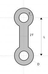
| + | == T8L – bone vertex == | ||
| + | [[Datei:Mill tracer T8L Bildschirmfoto.png|160px]] | ||
| + | *Parameters | ||
| + | ** '''L''' = length (hole center to hole center) | ||
| + | ** '''T''' = thickness (x1 on circles, x2 on connection bar) | ||
| + | ** '''D''' = diameter of holes | ||
| + | * Vertex element for the [[Egg-Bot]]. | ||
| + | |||
| + | <gallery caption="T8L – bone vertex"> | ||
| + | Datei:Mill tracer T8L EMC Bildschirmfoto.png|EMC Screen | ||
| + | Datei:Mill tracer T8L IMG 1825-1280.jpg|Routing test result | ||
| + | Datei:Mill tracer T8L IMG 1827-1280.jpg|Test M3 | ||
| + | Datei:Mill tracer T8L IMG 1828-1280.jpg|Test M3 | ||
| + | Datei:Mill tracer T88L Drawing.PNG|T88L - 3 hole vertex | ||
| + | Datei:Mill tracer T88L 15mm Bildschirmfoto.png|T88L in EMC | ||
| + | Datei:Mill tracer T88L IMG 1851.JPG|T88L's | ||
| + | Datei:Mill tracer T88L IMG 1858.JPG|Pantograph frame | ||
| + | </gallery> | ||
| + | <br/><br/> | ||
| + | |||
| + | |||
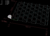
| + | == hex_wall == | ||
| + | [[Datei:Hex wall Bildschirmfoto.png|160px]] | ||
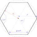
| + | * Gitter aus [http://de.wikipedia.org/wiki/Sechseck Sechsecken] via Processing --> g-Code | ||
| + | * Parameter | ||
| + | ** Breite des Sechsecks | ||
| + | ** Breite der Gitter-Stege | ||
| + | * just for fun ... Verwendung noch unklar, evtl. [http://de.wikipedia.org/w/index.php?title=Datei:Hans_Rosenthal_und_Monika_Sundermann_Dalli-Dalli.jpg] | ||
| + | * Material: Kunststoff-Abfälle, Dicke 3 mm | ||
| + | |||
| + | <gallery perrow="5"> | ||
| + | Datei:Sechseck-Zeichnung.png|Sechseck (Wikipedia) | ||
| + | Datei:Hex wall IMG 1882.JPG|Gefräst | ||
| + | Datei:Hex wall IMG 1880.JPG|Durchblick | ||
| + | Datei:Hex wall IMG 1877.JPG|6eck Reste - Ideen? | ||
| + | </gallery> | ||
| + | <br/><br/> | ||
| + | |||
| + | |||
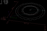
| + | == LED_Lamp == | ||
| + | [[Datei:LED Lamp 001 Bildschirmfoto 002.png|160px]] | ||
| + | * Lampenschirm für LED Lampe | ||
| + | * Konstruktion über Processing | ||
| + | * Material: Kunststoff-Abfälle, Dicke 3 mm | ||
| + | * just for fun | ||
| + | |||
| + | <gallery perrow="4"> | ||
| + | Datei:LED Lamp 001 Bildschirmfoto 002.png|EMC: Ringe | ||
| + | Datei:LED Lamp 001 IMG 1891.JPG|Ringe | ||
| + | Datei:LED Lamp 001 IMG 1893.JPG|Ringe | ||
| + | Datei:LED Lamp 001 Bildschirmfoto 001.png|EMC: Streifen | ||
| + | Datei:LED Lamp 001 IMG 1895.JPG|Streifen | ||
| + | Datei:LED Lamp 001 IMG 1898.JPG|Montage | ||
| + | Datei:LED Lamp 001 IMG 1899.JPG|fertig, leider verrechnet :-) | ||
| + | Datei:LED Lamp 001 IMG 1900.JPG|Hängt | ||
| + | </gallery> | ||
| + | <br/><br/> | ||
| + | |||
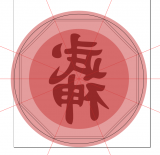
| + | == Bujinkan Logo == | ||
| + | [[Datei:Bujinkan.jpg|160px]] | ||
| + | <br/><br/> | ||
| + | === Toolchain für Gravur === | ||
| + | * '''Inkscape''' | ||
| + | ** Bitmap laden: [[Media:Bujin 001.png]] | ||
| + | ** Vektorisieren --> SVG Format: [[Media:BujinkanLogo 002.svg]] | ||
| + | * '''pyCAM''' | ||
| + | **SVG laden | ||
| + | ** Shift um Z = -0.5 mm<br>(Testweise: 2-phasig, -0.4 mm Vorschnitt und -0.5 mm Fertigschnitt) | ||
| + | ** Feedrate F100 | ||
| + | ** Trajectory control G61 P0.05 | ||
| + | ** Gravur Path --> g-Code | ||
| + | * '''EMC''' | ||
| + | ** Gravur-Stichel 90°, 16 kRPM, Feedrate F100 | ||
| + | === Material === | ||
| + | * Gravur: 6 mm [http://de.wikipedia.org/wiki/Polymethylmethacrylat Plexiglas] | ||
| + | * Gehäuse für Version 003: 10 mm [http://de.wikipedia.org/wiki/Mitteldichte_Holzfaserplatte MDF / Mitteldichte Holzfaserplatte] | ||
| + | ** kreisrund, Durchmesser 210 mm | ||
| + | * "Sandwich"-Bauweise aus 2 MDF Platten | ||
| + | ** Eine durchgehende Bodenplatte mit Bohrungen für 8 Schrauben | ||
| + | ** Eine Abdeck-Platte, in die das Plaxiglas 6,2 mm eingelassen ist | ||
| + | ** Hinter Plexiglas: Schwarzes Papier zur Steigerung des Kontrasts | ||
| + | <gallery perrow="4"> | ||
| + | Datei:BujinkanLogo Path AXL 001-c Bildschirmfoto.png|EMC Screen Version 002 | ||
| + | Datei:BujinkanLogo Path IMG 1902.JPG|Test in Kunststoff | ||
| + | Datei:Bujin 001.png|[[Media:BujinkanLogo 002.svg]] | ||
| + | Datei:Bujin IMG 1904.JPG|Tests und ... | ||
| + | Datei:Bujin IMG 1906.JPG|... Ergebnis in Plexiglas | ||
| + | Datei:Bujinkan Logo 003 001 Bildschirmfoto.png|Bujinkan Logo 003 - Entwurf für Gehäuse | ||
| + | Datei:Bujinkan Logo 003 100 4609.JPG|Gravur in 6mm Plexiglas | ||
| + | </gallery> | ||
| + | <br/><br/> | ||
| + | |||
| + | === LED Beleuchtung === | ||
| + | * Eine gleichmäßige Ausleuchtung für ca. 160 mm hohes Motiv war nach Tests mit 8 LEDs möglich | ||
| + | * Verschaltung in zwei Gruppen je 4 LEDs, Betrieb an 12 Volt ohne Vorwiderstand | ||
| + | * Mindestabstand zum Motiv und Abdeckung über den MDF-Rand sollten 15 mmm sein | ||
| + | ** Angestrebter Rand waren ~ 20 mm | ||
| + | ** für das Zusammenschrauben des Gehäuses sind entsprechende Zonen mit ca. 10 mm Materialdicke vorzusehen | ||
| + | ** Lösung über Kombination Kreis für Außenrand und Achteck für Plexiglas<br>[[Datei:Bujinkan Logo 003 001 Bildschirmfoto.png|160px]] | ||
| + | * Konstruktion in Inkscape über mehrere Ebenen für Holz und Plexiglas | ||
| + | * Realisierung der Schnittmuster für MDF über Processing Toolchain (''mill_tracer'') | ||
| + | ** Frontblende - Kreis mit achteckiger "Pocket" für das Plexiglas | ||
| + | ** Zwischenplatte mit Kreis mit achteckiger "Pocket" den Hintergrund plus Aussparung für Arduino | ||
| + | <br> | ||
| + | |||
| + | <gallery perrow="4"> | ||
| + | Datei:Bujinkan Logo 003 100 4719.JPG|Zwischenplatte | ||
| + | Datei:Bujinkan Logo 003 100 4720.JPG|... Oh, so Dharma? | ||
| + | </gallery> | ||
| + | <br/><br/> | ||
| + | |||
| + | == Open Source Hardware - Logo == | ||
| + | [[Datei:Oshw-logo-200-px.png]] | ||
| + | <br/><br/> | ||
| + | ''Toolchain'' | ||
| + | * '''Inkscape''' | ||
| + | ** Logo + Umriß in mehreren Ebenen in einer SVG Quelldatei | ||
| + | ** Logo als SVG übernehmen von http://oshwlogo.com/ | ||
| + | ** Logo spiegeln für Gravur auf der Unterseite (!) | ||
| + | ** SVG Format für jede Ebene getrennt speichern und in pyCAM übernehmen | ||
| + | * '''pyCAM''' | ||
| + | ** SVG laden | ||
| + | ** Shift um Z = -0,5 mm für Gravur oder -1.0 - -5,0 mm für Schnitte | ||
| + | ** Feedrate F400 | ||
| + | ** Gravur Path --> g-Code | ||
| + | * '''EMC''' | ||
| + | ** Gravur-Stichel, 10 - 20 kRPM | ||
| + | ** Schnitte | ||
| + | *** g-Code File erweitert um "step-down" Schleife (dZ = -1,0 mm) | ||
| + | *** Fräser 3,2 mm einschneidig, 10 kRPM | ||
| + | * '''LEDS''' | ||
| + | ** 3 mm rot aus der Hackerspace-Grabbelkiste | ||
| + | ** [[Media:Oshw-logo_IMG_1918.JPG|LED Bohr-Hilfe]] für kontrollierte senkrechte 3 mm Löcher | ||
| + | ** 10 LEDs in 2 Gruppen je 5 | ||
| + | ** gemessen: 2 V entspr. 16 mA | ||
| + | ** Betrieb mit 9 oder 12 Volt möglich ohne Vorwiderstand | ||
| + | |||
| + | <gallery perrow="4"> | ||
| + | Datei:Oshw-logo+cover 004 Gravur mirror Bildschirmfoto.png|Gravur in EMC | ||
| + | Datei:Oshw-logo_pyCAM_Bildschirmfoto.png|Erstes Cover in pyCAM | ||
| + | Datei:Oshw-logo_IMG_1909.JPG|Material, Plexi | ||
| + | Datei:Oshw-logo_IMG_1910.JPG|Gravur | ||
| + | Datei:Oshw-logo_IMG_1918.JPG|LED Bohr-Hilfe: senkrecht | ||
| + | Datei:Oshw-logo_IMG_1916.JPG|LED Löcher | ||
| + | Datei:Oshw-logo_IMG_1920.JPG|Test | ||
| + | Datei:Oshw-logo_IMG_1921.JPG|Blende 2 | ||
| + | </gallery> | ||
| + | |||
| + | <br><br> | ||
| + | === Open Source Hardware - Logo in MDF === | ||
| + | [[Datei:OSHW Logo-MDF EMC Bildschirmfoto.png|320px|none|thumb|EMC Screen]] | ||
| + | * '''OSHW Logo im Druckbett für [[Hackffm³RepRap]] 3D Drucker''' | ||
| + | ** Material: 10 mm MDF, [http://de.wikipedia.org/wiki/Mitteldichte_Holzfaserplatte Mitteldichte Holzfaserplatte] | ||
| + | ** Fräser: 2,1 mm, Spiralverzahnung, 10 kRPM, F400 | ||
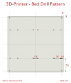
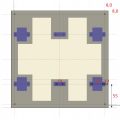
| + | * '''Bohrungen''' | ||
| + | ** zusätzlich Bohrungen zur Montage aller Elemente des Druckbetts, D 3,2 mm | ||
| + | ** Ecken: je 8 mm Abstand, D 3,2 mm | ||
| + | ** Montage-Linie: 55 mm vom oberen/unteren Rand | ||
| + | ** Lagerblöcke: 10 & 40 mm vom rechten, linken Rand, D 3,2 mm | ||
| + | ** Riemenhalter: mittig, 18 mm, D 3,2 mm | ||
| + | * '''Seiten-Ausschnitte''' | ||
| + | ** Weitere Reduzierung der Gewichts | ||
| + | ** OSHW Logo bleibt erhalten | ||
| + | |||
| + | <gallery perrow="5"> | ||
| + | Datei:OSHW Logo-MDF IMG 1925.JPG|Schnitt | ||
| + | Datei:OSHW Logo-MDF IMG 1926.JPG|fertig | ||
| + | Datei:3D-Bed drill pattern.png|Bohrungen | ||
| + | Datei:OSHW Logo-MDF IMG 1927.JPG|Bohrungen | ||
| + | Datei:OSHW Logo-MDF IMG 1928.JPG|Montage | ||
| + | Datei:OSHW Logo-MDF IMG 1932.JPG|Rest :-) | ||
| + | Datei:OSHW font cut 001 Bildschirmfoto.png|OSHW in EMC | ||
| + | Datei:OSHW font cut 001 IMG 1935.JPG|Fräsen | ||
| + | Datei:OSHW font cut 001 IMG 1936.JPG|Fräsen | ||
| + | Datei:OSHW font cut 001 IMG 1939.JPG|fertig | ||
| + | Datei:3D-Bed drill pattern 008 B Bildschirmfoto.png|Seiten-Ausschnitte in EMC ... | ||
| + | Datei:Mendel Y-Carriage CNC IMG 1949.JPG|und beim Fräsen | ||
| + | Datei:Mendel Y-Carriage CNC IMG 1950.JPG|Fertig | ||
| + | </gallery> | ||
| + | <br/><br/> | ||
| + | |||
| + | === MDF lackieren === | ||
| + | |||
| + | * '''Test mit dem OSWH Rest''' | ||
| + | ** 10 mm MDF | ||
| + | ** 2 x Grundierung, insbesondere den Rand | ||
| + | ** 1 x Acryl Lack | ||
| + | ** gleichmäßigere Ergebnisse mit Schaumstoff-Rolle statt Pinsel | ||
| + | |||
| + | <gallery perrow="5"> | ||
| + | Datei:OSHW Logo-MDF IMG 1932.JPG|Rest :-) | ||
| + | Datei:OSHW Logo MDF cut 100 4563.JPG|Grundierung + Acryl Lack | ||
| + | Datei:OSHW Logo MDF cut 100 4566.JPG|Grundierung 1 | ||
| + | Datei:OSHW Logo MDF cut 100 4569.JPG|Grundierung 2 | ||
| + | |||
| + | </gallery> | ||
| + | <br/><br/> | ||
| + | |||
| + | == Mendel - Y-Carriage == | ||
| + | [[Datei:Mendel Y-Carriage EMC Bildschirmfoto.png|320px|none|thumb|EMC Screen]] | ||
| + | <br/> | ||
| + | * '''Parameter''' | ||
| + | ** Material: 10 mm MDF, [http://de.wikipedia.org/wiki/Mitteldichte_Holzfaserplatte Mitteldichte Holzfaserplatte] | ||
| + | ** Fräser: 2,1 mm, Spiralverzahnung, 16 kRPM, Feedrate F500 | ||
| + | ** 2. Charge - August 2012: Fräser: 2,1 mm, Spiralverzahnung, 10 kRPM, Feedrate F500 | ||
| + | * '''Bohrungen''' | ||
| + | ** Konstruktion über Processing | ||
| + | ** zusätzlich Bohrungen zur Montage aller Elemente des Druckbetts, D 3,2 mm | ||
| + | ** Ecken: je 8 mm Abstand, D 3,2 mm | ||
| + | ** Montage-Linie: 55 mm vom oberen/unteren Rand | ||
| + | *** Lagerblöcke: 10 & 40 mm vom rechten/linken Rand, D 3,2 mm | ||
| + | *** Riemenhalter: mittig, 18 mm, D 3,2 mm | ||
| + | * '''Material-Einsparung''' | ||
| + | ** Konstruktion über Inkscape und pyCAM (Gravur-Modus) | ||
| + | ** Überstand 5 mm über alle Mendel-Elemente | ||
| + | ** Optimierung: Möglichst nur eine Fräs-Linie und kurze Wege | ||
| + | ** Zusätzliche "Z down" Schleife per Hand eingefüht: 7 x 1,6 mm | ||
| + | * '''Zeitaufwand''' | ||
| + | ** Bohren und Fräsen in einem Arbeitsgang je Carriage: ca. 20 Minuten + 10 Minuten Rüstzeit | ||
| + | ** Serienproduktion: 8 Carriages am 16.04.2012 | ||
| + | ** Aufgezeichnet mit [[HackffmActivitySensors]] - es war laut!<br>[[Datei:Mendel Y-Carriage noisy OpenMonday.png|320px|none|thumb|Geräuschlevel-Protokoll 16.04.2012]] | ||
| + | <br/> | ||
| + | <gallery perrow="4"> | ||
| + | Datei:Mendel Y-Carriage Inkscape 002.PNG|Konstruktion in Inkscape | ||
| + | Datei:Mendel Y-Carriage 2012-04-13 14.46.07.jpg|Fräsen | ||
| + | Datei:Mendel Y-Carriage 2012-04-13 15.00.34.jpg|Fertig | ||
| + | Datei:Mendel Y-Carriage IMG 1967.JPG|Serienproduktion ... | ||
| + | Datei:Mendel Y-Carriage IMG 1970.JPG|... 8 Carriages ... | ||
| + | Datei:Mendel Y-Carriage IMG 1972.JPG|... mit Heizbett | ||
| + | Datei:Mendel Y-Carriage IMG 1973.JPG|Heizbett | ||
| + | Datei:Mendel Y-Carriage IMG 1974.JPG|Heizbett Detail | ||
| + | Datei:Mendel Y-Carriage IMG 1987.JPG|Lager montiert @ hackffm³RepRap | ||
| + | Datei:Mendel Y-Carriage IMG 1989.JPG|Carriage montiert @ hackffm³RepRap | ||
| + | Datei:Mendel Y-Carriage IMG 1991.JPG|Heizbett montiert @ hackffm³RepRap | ||
| + | </gallery> | ||
| + | <br><br> | ||
| + | |||
| + | == Mendel - Acrylic Build Platform == | ||
| + | [[Datei:Acrylic Build Platform - EMC Bildschirmfoto-1.png|320px|none|thumb|EMC Screen]] | ||
| + | |||
| + | * Gravur in Acryl, nach dem Vorbild http://store.solidoodle.com/index.php?route=product/product&path=63&product_id=53 | ||
| + | * Tests mit unterschiedlichen Gravur-Tiefen | ||
| + | ** 0,050 mm, 0,025 mm, 0,015 mm und 0,007 mm (funktioniert nicht) | ||
| + | * Integration der [http://paulbourke.net/dataformats/hershey/ Hershey Fonts] in die Processing Toolchain | ||
| + | * Tested by [[Benutzer:Manupool|Manupool]] | ||
| + | |||
| + | <br/> | ||
| + | <gallery perrow="3"> | ||
| + | Datei:Acrylic Build Platform - EMC Bildschirmfoto-1.png|Tests mit unterschiedlichen Gravur-Tiefen | ||
| + | Datei:Acrylic Build Platform - EMC Bildschirmfoto-2.png|EMC bei der Arbeit | ||
| + | Datei:Acrylic Build Platform - EMC Bildschirmfoto-3.png|EMC ... | ||
| + | Datei:Acrylic Build Platform - 100 4706.JPG|Fräsen ... | ||
| + | Datei:Acrylic Build Platform - 100 4709.JPG|fast fertig ... | ||
| + | Datei:Foto2821.jpg|Tested by [[Benutzer:Manupool|Manupool]] | ||
| + | </gallery> | ||
| + | <br><br> | ||
| + | |||
| + | == Tests mit OpenSCAD == | ||
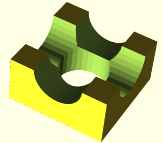
| + | [[Datei:Pycam 3D cut 001 pic OpenSCAD 002.png|320px|none|thumb|OpenSCAD Screen]] | ||
| + | <br/> | ||
| + | * '''Toolchain''' | ||
| + | ** OpenSCAD | ||
| + | *** cube() aus Script 'example001' abgeleitet, 50 x 50 x 25 mm³ | ||
| + | ** pyCAM | ||
| + | *** 1. Toolpath: remove material - "rough" | ||
| + | *** 2. Toolpath: cleanup - "finish" | ||
| + | ** EMC | ||
| + | *** Test mit Dämm-Schaum | ||
| + | *** 3 mm Fräser, zweischneidig | ||
| + | *** Feedrate F500 | ||
| + | |||
| + | <br/> | ||
| + | <gallery perrow="4"> | ||
| + | Datei:Pycam 3D cut 001 pic OpenSCAD 001.png|OpenSCAD Screen | ||
| + | Datei:Pycam 3D cut 001 pic rough.png|pyCAM "rough" | ||
| + | Datei:Pycam 3D cut 001 pic finish.png|pyCAM "finish" | ||
| + | Datei:Pycam 3D cut 001 pic EMC.png|EMC "finish" | ||
| + | Datei:Pycam 3D cut 001 100 4590.JPG|"rough" | ||
| + | Datei:Pycam 3D cut 001 100 4592.JPG|"finish" | ||
| + | </gallery> | ||
| + | <br> | ||
| + | |||
| + | OpenSCAD Script: | ||
| + | <nowiki>module example001() | ||
| + | { | ||
| + | function r_from_dia(d) = d / 2; | ||
| + | |||
| + | module rotcy(rot, r, h) { | ||
| + | rotate(90, rot) | ||
| + | cylinder(r = r, h = h, center = true); | ||
| + | } | ||
| + | |||
| + | difference() { | ||
| + | translate([0, 0, -12.5]) cube([50, 50, 25], center=true); | ||
| + | rotcy([0, 0, 0], cy_r, cy_h); | ||
| + | rotcy([1, 0, 0], cy_r, cy_h); | ||
| + | rotcy([0, 1, 0], cy_r, cy_h); | ||
| + | } | ||
| + | |||
| + | size = 50; | ||
| + | hole = 25; | ||
| + | |||
| + | cy_r = r_from_dia(hole); | ||
| + | cy_h = r_from_dia(size * 2.5); | ||
| + | } | ||
| + | |||
| + | example001();</nowiki> | ||
| + | <br> | ||
| + | |||
| + | |||
| + | == Stempel fräsen == | ||
| + | [[Datei:Hackerspace FFM Stamp reviewed.png|160px|none]] | ||
| + | * Tests für [[Hackerspace_Ffm_Stempel_und_T-Shirts]] | ||
| + | ** Als Material wurde echter Stempel-Gummi mit 2 mm Dicke benutzt. | ||
| + | ** das Motiv durfte nicht zu viele Details enthalten, da diese sonst durch den Fräser nicht mehr ausgeschnitten werden können. | ||
| + | ** Nach einigen Tests fiel die Entscheidung auf das Hackerspace FFM "favicon,ico" ([[HackFFM_Logo_2.0#favicon.ico]]) zusammen mit einem Schriftzug "hackffm". | ||
| + | * '''Setup für "''favicon.ico''"''': | ||
| + | ** Entwurf des Motivs in Inkscape incl. "Pocket" Ausschnitt ([[:Datei:Hackerspace FFM Stamp-favicon.svg]]) | ||
| + | ** 1 mm Fräser | ||
| + | ** Delta-Z -0.75 mm | ||
| + | ** Tiefe Z -1,5 mm | ||
| + | ** Drehzahl 16k RPM | ||
| + | ** Vorschub F200 | ||
| + | * '''Setup für "''hackffm''"''': | ||
| + | ** Entwurf des Motivs in Inkscape incl. "Pocket" Ausschnitt ([[:Datei:Hackerspace FFM Stamp-3a +0.55mm contour invers cut.svg]]) | ||
| + | ** Schriftart "Nimbus Sans - Bold condensed" | ||
| + | ** 0,55 mm Fräser | ||
| + | ** Delta-Z -0.50 mm | ||
| + | ** Tiefe Z -1,0 mm | ||
| + | ** Drehzahl 16k RPM | ||
| + | ** Vorschub F75 | ||
| + | |||
| + | |||
| + | <gallery perrow="5"> | ||
| + | Datei:Stamp Test OSHW EMC Bildschirmfoto-1.png|OSHW Logo (Contour) | ||
| + | Datei:Stamp Test OSHW EMC Bildschirmfoto-2.png|OSHW Logo (Pocket) | ||
| + | Datei:Stamp Test OSHW 2012-06-12 20.33.21.jpg|OSHW Logo - Stamp Test | ||
| + | Datei:Hackerspace FFM Stamp 2012-06-16 20.37.47.jpg|mehr Tests | ||
| + | Datei:Favicon 2011 128x128.png|favicon.ico | ||
| + | Datei:Favicon stamp test EMC-1.png|favicon.ico in EMC | ||
| + | Datei:Hackerspace FFM Stamp 2012-06-16 20.28.06.jpg|favicon fräsen | ||
| + | Datei:Hackerspace FFM Stamp-3a +0.55mm contour invers cut EMC.png|Schrift-Block in EMC | ||
| + | Datei:Hackerspace FFM Stamp 100 4762.JPG|... fertig | ||
| + | </gallery> | ||
| + | <br> | ||
| + | |||
| + | |||
| + | == Special Parts for Daniel == | ||
| + | {| class="wikitable" style="text-align: left; padding:6px 12px;" | ||
| + | |- | ||
| + | ! scope="row" style="text-align: left;!" | Material | ||
| + | | Plexiglas, 4,0 mm | ||
| + | |- | ||
| + | ! scope="row" style="text-align: left;!" | Fräser | ||
| + | | 3,0 mm, einschneidig / [http://mmetoolshop.homepage.t-online.de/shop/index.php?cPath=59_63&SESS=5260178d5d48ceb930646da5bc347385 mmetoolshop] | ||
| + | |- | ||
| + | ! scope="row" style="text-align: left;!" | Drehzahl | ||
| + | | 8 kRPM (Proxxon) | ||
| + | |- | ||
| + | ! scope="row" style="text-align: left;!" | Feedrate | ||
| + | | F200 [mm/min] | ||
| + | |- | ||
| + | ! scope="row" style="text-align: left;!" | Tiefe (dZ) | ||
| + | | -1.1 mm, 4 Runden | ||
| + | |} | ||
| + | |||
| + | |||
| + | {| class="wikitable" | ||
| + | |- | ||
| + | ! scope="row" style="text-align: left;!" | Material | ||
| + | | Pertinax Platinenmaterial 1,5 mm, einseitige Kupferbeschichtung nach oben / [http://mmetoolshop.homepage.t-online.de/shop/index.php?cPath=59_63&SESS=5260178d5d48ceb930646da5bc347385 MMEToolshop] | ||
| + | |- | ||
| + | ! scope="row" style="text-align: left;!" | Fräser | ||
| + | | 3,0 mm, spiralverzahnt / [http://mmetoolshop.homepage.t-online.de/shop/index.php?SESS=5260178d5d48ceb930646da5bc347385 MMEToolshop] | ||
| + | |- | ||
| + | ! scope="row" style="text-align: left;!" | Drehzahl | ||
| + | | 8 kRPM (Proxxon) | ||
| + | |- | ||
| + | ! scope="row" style="text-align: left;!" | Feedrate | ||
| + | | F200 [mm/min] | ||
| + | |- | ||
| + | ! scope="row" style="text-align: left;!" | Tiefe (dZ) | ||
| + | | -1.7 mm, 1 Runde | ||
| + | |} | ||
| + | |||
| + | |||
| + | * Plexi, 4mm | ||
| + | ** 3mm einschneidiger Fräser | ||
| + | ** F200 [mm/min] | ||
| + | ** dZ 1.1mm (4 Runden) | ||
| + | * Pertinax 1.5mm mit Kupferbeschichtung nach oben | ||
| + | ** 3mm spiralverzahnter Fräser | ||
| + | ** F200 [mm/min] | ||
| + | ** dZ 1.7mm (1 Runde) | ||
| + | |||
| + | |||
| + | <gallery perrow="5"> | ||
| + | Datei:Stamp Test OSHW EMC Bildschirmfoto-1.png|OSHW Logo (Contour) | ||
| + | </gallery> | ||
| + | <br> | ||
| + | |||
| + | == Slots ("Langlöcher") == | ||
| + | '''CNC_slot(x, y, w, h)''' | ||
| + | * Automatically detects vertical and hoizontal slots | ||
| + | * Circular drill if width == height | ||
| + | * Clockwise drilling | ||
| + | * Combination of arc (G02) and straight (G01) moves | ||
| + | * Continuous Z drill-down to z_cut using 1 x dz per round | ||
| + | * One final round will be on Z-level z_cut | ||
| + | |||
| + | <gallery perrow="5"> | ||
| + | Datei:CNC slot 001.png|cnc_slot schematics | ||
| + | Datei:CNC Slot Bildschirmfoto-2.png|EMC Screen with test slots | ||
| + | Datei:CNC slot IMG 2037.JPG|Slot mill tests | ||
| + | Datei:CNC slot IMG 2038.JPG|Slot mill tests | ||
| + | </gallery> | ||
| + | <br> | ||
| + | |||
| + | == X-Plate for PrintrBot == | ||
| + | * special material: compound of | ||
| + | ** 0.3 mm aluminium | ||
| + | ** 2.5 mm polyethylene | ||
| + | ** 0.3 mm aluminium | ||
| + | * special Z-down pattern with adjusted feedrates | ||
| + | ** 0.1 mm dZ with feedrate F100 [mm/min] for aluminium | ||
| + | ** 2.5 mm dZ with feedrate F150 [mm/min] for polyethylene | ||
| + | * for | ||
| + | ** slots: ''cnc_alu_pe_slot(float x, float y, float w, float h)'' | ||
| + | ** drilling holes: ''cnc_alu_pe_drill(float x, float y, float D)'' | ||
| + | |||
| + | |||
| + | <gallery perrow="5"> | ||
| + | Datei:Printrbot Lochbild Quadrant vorn links.JPG|X-plate schematics (detail) | ||
| + | Datei:Printrbot Lochbild Übersicht.JPG|X-plate schematics (detail) | ||
| + | Datei:CNC slot IMG 2037.JPG|Mill tests with compound material | ||
| + | Datei:IMAG0101.jpg|Router setup for mass production ;-) | ||
| + | Datei:IMAG0102.jpg|Tests | ||
| + | Datei:IMAG0105.jpg|Tests | ||
| + | Datei:Printrbot IMAG0107.jpg|First full plate | ||
| + | </gallery> | ||
| + | <br> | ||
| + | |||
| + | |||
| + | == Pockets für Kugellager == | ||
| + | Ein paar Prototyp-Halterungen für [[Benutzer:Snow]] aus Holz für ein Roboter-Projekt. | ||
| + | * Feedrate 300 | ||
| + | * dZ -1.25mm | ||
| + | |||
| + | |||
| + | <gallery perrow="5"> | ||
| + | Datei:Mill tracer 019 Snow Kugellager 001 EMC 001.png|g-Code Ansicht EMC | ||
| + | Datei:Mill tracer 019 Snow Kugellager 001 IMAG0700.jpg|Prototyp vom Prototyp | ||
| + | Datei:Mill tracer 019 Snow Kugellager 001 IMAG0721.jpg|aus MDF | ||
| + | Datei:Mill tracer 019 Snow Kugellager 002 IMAG0720.jpg|Fertigung | ||
| + | Datei:Mill tracer 019 Snow Kugellager 002 IMAG0717.jpg|mit Trennmarken für die Säge | ||
| + | Datei:Mill tracer 019 Snow Kugellager 002 IMAG0725.jpg|gesägt und | ||
| + | Datei:Mill tracer 019 Snow Kugellager 002 IMAG0732.jpg|gebohrt | ||
| + | </gallery> | ||
| + | <br> | ||
| + | |||
| + | |||
| + | == CNC Pause Juni-? 2013 == | ||
| + | Die CNC-Fräse wird von Daniel in einem Projekt gebraucht. | ||
| + | |||
| + | Daher ist erstmal Pause ... vielen Dank für die Dauer-Leihgabe. | ||
| + | |||
| + | |||
| + | <gallery perrow="5"> | ||
| + | Datei:Mill tracer 019 Snow Kugellager 002 IMAG0722.jpg|Stand Verkabelung beim Abbau | ||
| + | </gallery> | ||
| + | <br> | ||
| + | |||
| + | = Links & more infos = | ||
| + | * '''Community''' | ||
| + | ** [http://dingfabrik.de/geraete/stepfour-basic-540/ CNC Seite der DingFabrik Köln], Danke für die Infos, Habo | ||
| + | * '''CNC Hardware''' | ||
| + | ** [http://groups.google.com/group/zen-toolworks/topics?hl=en&start=50&sa=N Zen Toolworks Google group] | ||
| + | ** [http://wiki.zentoolworks.com/index.php/Main_Page ZEN Toolworks Wiki] | ||
| + | ** [http://pminmo.com/home-and-limit-switches?tmpl=component&print=1&page= Home amd Limit Switches on LPT port] | ||
| + | * '''Fräser und Werkzeuge''' | ||
| + | ** [http://www.vhf.eu/de/Werkzeuge VHF - Hartmetall- und Diamantwerkzeuge mit Infos] | ||
| + | ** [http://www.gis-tec.com/deutsch/d_fraeser___start.htm GIS tec] | ||
| + | * '''g-Code & Software''' | ||
| + | ** [http://linuxcnc.org/docs/html/gcode_main.html The EMC2 G Code Language] | ||
| + | ** [http://lcamtuf.coredump.cx/guerrilla_cnc1.shtml Guerrilla guide to CNC machining] | ||
| + | ** [http://cnccookbook.com/CCCNCGCodeSubprograms.htm g-Code Subprogram and Macro Calls] | ||
| + | ** [http://pycam.sourceforge.net/download.html pyCAM] | ||
[[Kategorie:Projekte]] | [[Kategorie:Projekte]] | ||
Aktuelle Version vom 4. November 2013, 22:16 Uhr
Inhaltsverzeichnis
- 1 Info zur Zen Toolworks 1212
- 2 CNC Revival project
- 3 Production mode
- 3.1 Inkscape g-code Export
- 3.2 Bohren der LED Platinen für das Buntich Projekt
- 3.3 Platinen fräsen und bohren
- 3.4 XYZ Blinkenlights for CNC Mills
- 3.5 Drawbot Logo
- 3.6 Kissen / Gußform Test
- 3.7 Drawbot Gondel-Teil - OpenSCAD
- 3.8 Buntich Aussparungen für Kabelkanäle
- 3.9 g-Codes G02 & G03 - Bögen
- 3.10 Tests mit pycam
- 3.11 Neue Fräser-Aufnahme und Tests 9 mm Multiplex Sperrholz
- 3.12 Egg-Bot Schild
- 3.13 Egg-Bot Y-Motor plate
- 3.14 T8L – bone vertex
- 3.15 hex_wall
- 3.16 LED_Lamp
- 3.17 Bujinkan Logo
- 3.18 Open Source Hardware - Logo
- 3.19 Mendel - Y-Carriage
- 3.20 Mendel - Acrylic Build Platform
- 3.21 Tests mit OpenSCAD
- 3.22 Stempel fräsen
- 3.23 Special Parts for Daniel
- 3.24 Slots ("Langlöcher")
- 3.25 X-Plate for PrintrBot
- 3.26 Pockets für Kugellager
- 3.27 CNC Pause Juni-? 2013
- 4 Links & more infos
Info zur Zen Toolworks 1212
- Daniels Leihgabe an den Hackerspace Ffm
- Typ Zen Toolworks 12x12 Inch
- Hersteller: Zen Toolworks
- Zen Toolworks CNC
CNC Revival project
Ziele
- Dezember 2011 - Februar 2012
- Fräse betriebsbereit und getestet
- Materialen
- Epoxy / Glasfaser / Platinen-Herstellung
- Holz
- Acryl
- Holz
- Aluminium ?
- Platz in der Werkstatt wg.
- Lärm
- Abzug / Entlüftung
- Staub
Hardware, Software
- Anschluß zunächst über Parallel-Port / Centronics
- geplant: USB Interface
- Betrieb mit freier Software
- Linux / Ubuntu
- Logon: CNCuser
- EMC
- EMC on Ubuntu Live CD (erfolgreich getestet am 10.12.2011 / CNC and 3D Dual-Boot PC)
- EMC forum / emcinfo.pl
- CNC and 3D Dual-Boot PC
- Spannungsversorgung
- separates Netzteil 5 Volt ersetzen durch Spannungsregler / 7805 und Anschluß an 12 Volt Haupt-Versorgung
- Home End-Stopps / Max. End-Stopps
- optisch / mechanisch?
Tests am 10.12.2011
Joypad Steuerung
- 14.12.2011
- Konfiguration eines Logitech Logitech Dual Action Joypad an EMC zu Steuerung der X, Y, Z Achsen
- 2 Geschwindigkeiten über Buttons wählbar.
- Joypad auf wiki.linuxcnc.org
Production mode
Inkscape g-code Export
- 14.12.2011
- Inkscape unter Ubuntu
- InkscapeHowto auf wiki.linuxcnc.org
- Export Plug-in für Inkscape
- Test-Datei Walking Camel von http://www.clker.com
Bohren der LED Platinen für das Buntich Projekt
- Massen-Bohrung für das Buntich Projekt
- je 4 Bohrungen je LED Platine
- Abstand Y: 1/10 Zoll = 2.54 mm
- Abstand X: 21,86 mm
- Bohr-Tiefe 2.5 mm
feed-rate F = 50-70 mm / min., Rückzug 150 mm / min.
- 18 Platinen, je 6 Buntich-Pixel, je 4 Löcher = 432 Löcher
Beispiel g-Code, per Text-Editor
%
(Bohren der LED Platinen für das Buntich Projekt)
(AXL für Hackerspace FFM, 17.12.2011)
M3
(Header end.)
G21 (All units in mm)

G00 X0.0 Y0.0 Z-0.0
G01 Z-2.5 F70
G00 Z-0.0

G00 Y+2.54
G01 Z-2.5 F70
G00 Z-0.0

G00 Y+5.08
G01 Z-2.5 F70
[...]

G00 X21.86 Y0.0

G01 Z-2.5 F70
G00 Z-0.0
[...]
Platinen fräsen und bohren
- CAD für PCB Entwurf: Win Layout von Abacom
- Bohren
- Ausgabe im Excellon Format
- Umwandlung über Excellon to G-Code Convertor
- Fräsen
- HPGL Export und Konvertierung in g-Code mit Inkscape
- (siehe Zen Toolworks CNC Fräse#Inkscape g-code Export)
XYZ Blinkenlights for CNC Mills
- LED-Circles für die X-, Y-, Z-Achse
- Bohrvorlage für 5 oder 3 mm LED-Circles in Processing
- Ausgabe der g-Codes direkt aus Processing
Drawbot Logo
- Ausgabe des Drawbot Fonts per Processing in g-Code
- Fräsen in Bastel-Kunststoff (grau) und Acryl
- Fräs-Test für ein Teil des Prusa Air
- Zen Toolworks CNC
Kissen / Gußform Test
- Fräsen einer Kissen-Form in Schaustoff
- Erstellen des G-Code mit Processing als Überlagerung von zwei Sinus-Funktionen für die Z-Achse ("Tiefe")
- Anwendung: Guß-Vorlage für Lautsprecher-Boxen
[...]
  for (float iy=0; iy <= my; iy += w) {
    s.add(new String("G00 Z" + fpp(h_save)));
    s.add(new String("G00 X0 Y" + fpp(iy)));

    float ky = sin((iy / my) * pi);

    for (float ix=0; ix <= mx; ix += w) {
      float kx = sin((ix / mx) * pi);
      z = h1 * kx * ky;
      s.add(new String("G01 X" + fpp(ix) + " Z" + fpp(z) + " F" + fpp(f)));
    }
  }
[...]
Drawbot Gondel-Teil - OpenSCAD
- Fräsen eines in OpenSCAD konstruierten Teils aus Kunststoff
- OpenSCAD Export als 2D DXF Datei - s.u.
- Konvertierung in g-Code mit Inkscape
OpenSCAD 3D zu 2D Konvertierung
[...]
// projection(cut=true) for DXF extrude
projection(cut=true) rotate([180,0,0]) {

    [... 3D parts here ...]

} // projection(cut=true) for DXF extrude
Probleme
- DXF Import
- Pfad wird beim Export nicht zusammengeführt
- "händische" Aufbereitung nötig, u.a. per Shell mittels:
cat PenDisc_V_003_combined_paths_0006.ngc|grep "G00 X"|awk '{print "G01 " $2 " " $3 " F80"}' > PenDisc_V_003_combined_paths_0006_filter.ngc
- Dimensionen
- OpenSCAD Modell hat Breite des Fräsers nicht beachtet (Radius 1.1 mm)
rm=1.1;		// radius mill tool
rh1=4;		// center hole
rh2=1.5;	// holes
[...]
cylinder(r=rh2-rm, h=10, center=true, $fn=20);
- Zen Toolworks CNC
Buntich Aussparungen für Kabelkanäle
Buntich Datenleitungen
- Fräsen rechteckiger Aussparungen in die Buntich Kabelkanäle
- Direktes Editieren des G-Code per Text-Editor
- Zen Toolworks CNC
Buntich Datenleitungen - g-Code
%
(Bohren der Kabelkanäle für das Buntich Projekt)
(AXL für Hackerspace FFM, 07.01.2012)
M3
(Header end.)
G21 (All units in mm)

G00 Z+1.0

G00 X+0.0 Y+0.0
G01 Z-2.5 F160
G01 Y+19 F160
G01 X+8 F160
G01 Y+0 F160
G01 X+0 F160

G00 Z+1.0

G00 X+18.0 Y+0.0
G01 Z-2.5 F160
G01 Y+19 F160
G01 X+26 F160
G01 Y+0 F160
G01 X+18 F160

G00 Z+1.0

G00 X0.0 Y0.0

(end)
%
Buntich 4mm Stecker
- 1 Loch 4mm, 1 Langloch 5mm x 4mm
- gefräst mit 2mm Fräser
Buntich Kabeldurchführung
- 3 Schlitze für Flachband-Kabel
- 2 x 2 Schlitze für Zugentlastung 10-polige Buches für Wannenstecker
- Muster 16 mal in Kebelkanal eingefräst
- Zen Toolworks CNC
g-Codes G02 & G03 - Bögen
- g-Code infos
- G02 - clockwise arc
- G03 - conter-clockwise arc
- Parameter I, J und K - Bogen-Zentrum X, Y und Z
- Test mit Processing: Bohrungen, Langlöcher, Rechtecke mit Radius fräsen
- g-Codes G02 & G03 - Bögen
cnc_path() & Egg-Bot Prototyp
- Processing-Funktion cnc_path() erlaubt das Fräsen nach Pfaden incl. abgerundeter Ecken
- Aktuelle Version: Nur 90° Schritte möglich
- Außen- und Innen-Radien werden individuell berechnet und mit "echten" Bögen (g-Code G02/G03) gefräst
- erste Anwendung: Rahmenteile für den Egg-Bot Prototyp
- Eggbot Prototyp
Tests mit pycam
Installation unter Ubuntu
sudo apt-get install python-gtk2 python-opengl python-gtkglext1 python-rsvg python-pyode python-guppy
sudo apt-get install inkscape pstoedit
Test-Fräsen
- CNC Piggie
Neue Fräser-Aufnahme und Tests 9 mm Multiplex Sperrholz
- Die neue Fräser-Aufnahme reicht deutlich näher an den Frästisch - Danke, Lötmichel
- Tests mit Version 1 für die Proxxon Bohrmaschine und 9 mm Multiplex Sperrholz
- Version 2 - mit neuem Motor - in Arbeit
- CNC Piggie
Egg-Bot Schild
- 3-Teiliges Schild für den Egg-Bot:
- Unterer Rahmen für Aufnahme des Glas-Teils + LED (g-Code via Processing)
- Abdeck-Rahmen (g-Code via Processing)
- Graviertes Glas-Teil (g-Code via InkScape --> pyCAM)
- Font: Century Schoolbook L (Century Type Family)
- Egg-Bot Schild
Egg-Bot Y-Motor plate
- Ersatz für ein Fischertechnik© Teil im Prototyp
- 9 mm Multiplex Sperrholz
- Aufnahme für NEMA 14 Stepper mit versenktem Lagerblock und 12 mm Langlöchern
- Schlitze zur Führung auf dem Egg-Bot Rahmen
- Konstruktion via Processing g-Code Framework
- Egg-Bot Y-Motor plate
T8L – bone vertex
- Parameters
- L = length (hole center to hole center)
- T = thickness (x1 on circles, x2 on connection bar)
- D = diameter of holes
- Vertex element for the Egg-Bot.
- T8L – bone vertex
hex_wall
- Gitter aus Sechsecken via Processing --> g-Code
- Parameter
- Breite des Sechsecks
- Breite der Gitter-Stege
- just for fun ... Verwendung noch unklar, evtl. [1]
- Material: Kunststoff-Abfälle, Dicke 3 mm
LED_Lamp
- Lampenschirm für LED Lampe
- Konstruktion über Processing
- Material: Kunststoff-Abfälle, Dicke 3 mm
- just for fun
Bujinkan Logo
Toolchain für Gravur
- Inkscape
- Bitmap laden: Media:Bujin 001.png
- Vektorisieren --> SVG Format: Media:BujinkanLogo 002.svg
- pyCAM
- SVG laden
- Shift um Z = -0.5 mm
(Testweise: 2-phasig, -0.4 mm Vorschnitt und -0.5 mm Fertigschnitt) - Feedrate F100
- Trajectory control G61 P0.05
- Gravur Path --> g-Code
- EMC
- Gravur-Stichel 90°, 16 kRPM, Feedrate F100
Material
- Gravur: 6 mm Plexiglas
- Gehäuse für Version 003: 10 mm MDF / Mitteldichte Holzfaserplatte
- kreisrund, Durchmesser 210 mm
- "Sandwich"-Bauweise aus 2 MDF Platten
- Eine durchgehende Bodenplatte mit Bohrungen für 8 Schrauben
- Eine Abdeck-Platte, in die das Plaxiglas 6,2 mm eingelassen ist
- Hinter Plexiglas: Schwarzes Papier zur Steigerung des Kontrasts
LED Beleuchtung
- Eine gleichmäßige Ausleuchtung für ca. 160 mm hohes Motiv war nach Tests mit 8 LEDs möglich
- Verschaltung in zwei Gruppen je 4 LEDs, Betrieb an 12 Volt ohne Vorwiderstand
- Mindestabstand zum Motiv und Abdeckung über den MDF-Rand sollten 15 mmm sein
- Konstruktion in Inkscape über mehrere Ebenen für Holz und Plexiglas
- Realisierung der Schnittmuster für MDF über Processing Toolchain (mill_tracer)
- Frontblende - Kreis mit achteckiger "Pocket" für das Plexiglas
- Zwischenplatte mit Kreis mit achteckiger "Pocket" den Hintergrund plus Aussparung für Arduino
Open Source Hardware - Logo
- Inkscape
- Logo + Umriß in mehreren Ebenen in einer SVG Quelldatei
- Logo als SVG übernehmen von http://oshwlogo.com/
- Logo spiegeln für Gravur auf der Unterseite (!)
- SVG Format für jede Ebene getrennt speichern und in pyCAM übernehmen
- pyCAM
- SVG laden
- Shift um Z = -0,5 mm für Gravur oder -1.0 - -5,0 mm für Schnitte
- Feedrate F400
- Gravur Path --> g-Code
- EMC
- Gravur-Stichel, 10 - 20 kRPM
- Schnitte
- g-Code File erweitert um "step-down" Schleife (dZ = -1,0 mm)
- Fräser 3,2 mm einschneidig, 10 kRPM
- LEDS
- 3 mm rot aus der Hackerspace-Grabbelkiste
- LED Bohr-Hilfe für kontrollierte senkrechte 3 mm Löcher
- 10 LEDs in 2 Gruppen je 5
- gemessen: 2 V entspr. 16 mA
- Betrieb mit 9 oder 12 Volt möglich ohne Vorwiderstand
Open Source Hardware - Logo in MDF
- OSHW Logo im Druckbett für Hackffm³RepRap 3D Drucker
- Material: 10 mm MDF, Mitteldichte Holzfaserplatte
- Fräser: 2,1 mm, Spiralverzahnung, 10 kRPM, F400
- Bohrungen
- zusätzlich Bohrungen zur Montage aller Elemente des Druckbetts, D 3,2 mm
- Ecken: je 8 mm Abstand, D 3,2 mm
- Montage-Linie: 55 mm vom oberen/unteren Rand
- Lagerblöcke: 10 & 40 mm vom rechten, linken Rand, D 3,2 mm
- Riemenhalter: mittig, 18 mm, D 3,2 mm
- Seiten-Ausschnitte
- Weitere Reduzierung der Gewichts
- OSHW Logo bleibt erhalten
MDF lackieren
- Test mit dem OSWH Rest
- 10 mm MDF
- 2 x Grundierung, insbesondere den Rand
- 1 x Acryl Lack
- gleichmäßigere Ergebnisse mit Schaumstoff-Rolle statt Pinsel
Mendel - Y-Carriage
- Parameter
- Material: 10 mm MDF, Mitteldichte Holzfaserplatte
- Fräser: 2,1 mm, Spiralverzahnung, 16 kRPM, Feedrate F500
- 2. Charge - August 2012: Fräser: 2,1 mm, Spiralverzahnung, 10 kRPM, Feedrate F500
- Bohrungen
- Konstruktion über Processing
- zusätzlich Bohrungen zur Montage aller Elemente des Druckbetts, D 3,2 mm
- Ecken: je 8 mm Abstand, D 3,2 mm
- Montage-Linie: 55 mm vom oberen/unteren Rand
- Lagerblöcke: 10 & 40 mm vom rechten/linken Rand, D 3,2 mm
- Riemenhalter: mittig, 18 mm, D 3,2 mm
- Material-Einsparung
- Konstruktion über Inkscape und pyCAM (Gravur-Modus)
- Überstand 5 mm über alle Mendel-Elemente
- Optimierung: Möglichst nur eine Fräs-Linie und kurze Wege
- Zusätzliche "Z down" Schleife per Hand eingefüht: 7 x 1,6 mm
- Zeitaufwand
- Bohren und Fräsen in einem Arbeitsgang je Carriage: ca. 20 Minuten + 10 Minuten Rüstzeit
- Serienproduktion: 8 Carriages am 16.04.2012
- Aufgezeichnet mit HackffmActivitySensors - es war laut!
Mendel - Acrylic Build Platform
- Gravur in Acryl, nach dem Vorbild http://store.solidoodle.com/index.php?route=product/product&path=63&product_id=53
- Tests mit unterschiedlichen Gravur-Tiefen
- 0,050 mm, 0,025 mm, 0,015 mm und 0,007 mm (funktioniert nicht)
- Integration der Hershey Fonts in die Processing Toolchain
- Tested by Manupool
Tested by Manupool
Tests mit OpenSCAD
- Toolchain
- OpenSCAD
- cube() aus Script 'example001' abgeleitet, 50 x 50 x 25 mm³
- pyCAM
- 1. Toolpath: remove material - "rough"
- 2. Toolpath: cleanup - "finish"
- EMC
- Test mit Dämm-Schaum
- 3 mm Fräser, zweischneidig
- Feedrate F500
- OpenSCAD
OpenSCAD Script:
module example001()
{
	function r_from_dia(d) = d / 2;

	module rotcy(rot, r, h) {
		rotate(90, rot)
			cylinder(r = r, h = h, center = true);
	}

	difference() {
		translate([0, 0, -12.5]) cube([50, 50, 25], center=true);
		rotcy([0, 0, 0], cy_r, cy_h);
		rotcy([1, 0, 0], cy_r, cy_h);
		rotcy([0, 1, 0], cy_r, cy_h);
	}

	size = 50;
	hole = 25;

	cy_r = r_from_dia(hole);
	cy_h = r_from_dia(size * 2.5);
}

example001();
Stempel fräsen
- Tests für Hackerspace_Ffm_Stempel_und_T-Shirts
- Als Material wurde echter Stempel-Gummi mit 2 mm Dicke benutzt.
- das Motiv durfte nicht zu viele Details enthalten, da diese sonst durch den Fräser nicht mehr ausgeschnitten werden können.
- Nach einigen Tests fiel die Entscheidung auf das Hackerspace FFM "favicon,ico" (HackFFM_Logo_2.0#favicon.ico) zusammen mit einem Schriftzug "hackffm".
- Setup für "favicon.ico":
- Entwurf des Motivs in Inkscape incl. "Pocket" Ausschnitt (Datei:Hackerspace FFM Stamp-favicon.svg)
- 1 mm Fräser
- Delta-Z -0.75 mm
- Tiefe Z -1,5 mm
- Drehzahl 16k RPM
- Vorschub F200
- Setup für "hackffm":
- Entwurf des Motivs in Inkscape incl. "Pocket" Ausschnitt (Datei:Hackerspace FFM Stamp-3a +0.55mm contour invers cut.svg)
- Schriftart "Nimbus Sans - Bold condensed"
- 0,55 mm Fräser
- Delta-Z -0.50 mm
- Tiefe Z -1,0 mm
- Drehzahl 16k RPM
- Vorschub F75
Special Parts for Daniel
| Material | Plexiglas, 4,0 mm |
|---|---|
| Fräser | 3,0 mm, einschneidig / mmetoolshop |
| Drehzahl | 8 kRPM (Proxxon) |
| Feedrate | F200 [mm/min] |
| Tiefe (dZ) | -1.1 mm, 4 Runden |
| Material | Pertinax Platinenmaterial 1,5 mm, einseitige Kupferbeschichtung nach oben / MMEToolshop |
|---|---|
| Fräser | 3,0 mm, spiralverzahnt / MMEToolshop |
| Drehzahl | 8 kRPM (Proxxon) |
| Feedrate | F200 [mm/min] |
| Tiefe (dZ) | -1.7 mm, 1 Runde |
- Plexi, 4mm
- 3mm einschneidiger Fräser
- F200 [mm/min]
- dZ 1.1mm (4 Runden)
- Pertinax 1.5mm mit Kupferbeschichtung nach oben
- 3mm spiralverzahnter Fräser
- F200 [mm/min]
- dZ 1.7mm (1 Runde)
Slots ("Langlöcher")
CNC_slot(x, y, w, h)
- Automatically detects vertical and hoizontal slots
- Circular drill if width == height
- Clockwise drilling
- Combination of arc (G02) and straight (G01) moves
- Continuous Z drill-down to z_cut using 1 x dz per round
- One final round will be on Z-level z_cut
X-Plate for PrintrBot
- special material: compound of
- 0.3 mm aluminium
- 2.5 mm polyethylene
- 0.3 mm aluminium
- special Z-down pattern with adjusted feedrates
- 0.1 mm dZ with feedrate F100 [mm/min] for aluminium
- 2.5 mm dZ with feedrate F150 [mm/min] for polyethylene
- for
- slots: cnc_alu_pe_slot(float x, float y, float w, float h)
- drilling holes: cnc_alu_pe_drill(float x, float y, float D)
Pockets für Kugellager
Ein paar Prototyp-Halterungen für Benutzer:Snow aus Holz für ein Roboter-Projekt.
- Feedrate 300
- dZ -1.25mm
CNC Pause Juni-? 2013
Die CNC-Fräse wird von Daniel in einem Projekt gebraucht.
Daher ist erstmal Pause ... vielen Dank für die Dauer-Leihgabe.
Links & more infos
- Community
- CNC Seite der DingFabrik Köln, Danke für die Infos, Habo
- CNC Hardware
- Fräser und Werkzeuge
- g-Code & Software


