| (53 dazwischenliegende Versionen desselben Benutzers werden nicht angezeigt) | |||
| Zeile 1: | Zeile 1: | ||
| + | Um Bilder für Bauteile zu erstellen gibts hier eine kleine [[MikroEckeBauteilBildErstellen | Anleitung]] | ||
| + | |||
=== Boards === | === Boards === | ||
{| class="wikitable" | {| class="wikitable" | ||
! Bild | ! Bild | ||
| + | ! n | ||
! Name | ! Name | ||
! Werte | ! Werte | ||
! Pinouts | ! Pinouts | ||
| + | ! Link | ||
| + | ! Beschreibung | ||
|- | |- | ||
| [[Datei:ArduinoProMini.jpg|100px]] | | [[Datei:ArduinoProMini.jpg|100px]] | ||
| + | | | ||
| Arduino Pro Mini | | Arduino Pro Mini | ||
| − | | | + | | 3.3 V <br> 5 V |
| − | | [http://www.pighixxx. | + | | [http://www.pighixxx.net/test/portfolio-items/pro-mini-new-version/?portfolioID=314] |
| + | | | ||
| + | | | ||
| + | |- | ||
| + | | [[Datei:Arduino_nano.jpg|100px]] | ||
| + | | 1 | ||
| + | | Arduino Nano | ||
| + | | 5V | ||
| + | | [http://www.pighixxx.net/test/portfolio-items/nano/?portfolioID=314] | ||
| + | | | ||
| + | | | ||
| + | |- | ||
| + | | [[Datei:DigisparkKickstarter.jpg|100px]] | ||
| + | | 1 | ||
| + | | Digispark Kickstarter | ||
| + | | 5V | ||
| + | | | ||
| + | | [https://www.kickstarter.com/projects/digistump/digispark-the-tiny-arduino-enabled-usb-dev-board?lang=de] | ||
| + | | | ||
| + | |- | ||
| + | | [[Datei:ProMicro.jpg|100px]] | ||
| + | | 1 | ||
| + | | [[ArduinoProMicro|Arduino Pro Micro]] | ||
| + | | 5V / 16MHz | ||
| + | | | ||
| + | | | ||
| + | | ATmega32U4 mit integriertem USB um als Maus oder Tastatur verwendet zu werden | ||
|} | |} | ||
| Zeile 26: | Zeile 58: | ||
| 8bit 1.8-5.5 volts | | 8bit 1.8-5.5 volts | ||
| [http://www.microchip.com/wwwproducts/en/ATmega328P] | | [http://www.microchip.com/wwwproducts/en/ATmega328P] | ||
| − | | [http://www.pighixxx. | + | | [http://www.pighixxx.net/test/portfolio-items/atmega328/?portfolioID=337] |
|} | |} | ||
| Zeile 47: | Zeile 79: | ||
{| class="wikitable" | {| class="wikitable" | ||
! Bild | ! Bild | ||
| + | ! n | ||
! Name | ! Name | ||
! Channel | ! Channel | ||
| Zeile 53: | Zeile 86: | ||
|- | |- | ||
|[[Datei:TO-220-G-D-S.jpg|100px]] | |[[Datei:TO-220-G-D-S.jpg|100px]] | ||
| + | | | ||
| IRLB8721 | | IRLB8721 | ||
| N | | N | ||
| Zeile 59: | Zeile 93: | ||
|- | |- | ||
|[[Datei:TO-220-G-D-S.jpg|100px]] | |[[Datei:TO-220-G-D-S.jpg|100px]] | ||
| + | | 3 | ||
| + | | HY5204W | ||
| + | | N | ||
| + | | 40V 320A <br>R<sub>DS(on)</sub> = 1.3mOhm at V<sub>GS</sub> = 10V<br>TO-247 | ||
| + | | [http://www.dianyuan.com/upload/community/2014/06/19/1403163973-71892.pdf] | ||
| + | |- | ||
| + | |[[Datei:TO-220-G-D-S.jpg|100px]] | ||
| + | | | ||
| FQP27P06 | | FQP27P06 | ||
| P | | P | ||
| Zeile 73: | Zeile 115: | ||
! Pinouts | ! Pinouts | ||
|- | |- | ||
| − | |[[Datei: | + | |[[Datei:Nrf24l01_normal.png|100px]] |
| nRF24L01 | | nRF24L01 | ||
| 1.9 to 3.6V 2Mbps 2.4GHz | | 1.9 to 3.6V 2Mbps 2.4GHz | ||
| Zeile 79: | Zeile 121: | ||
| [http://starter-kit.nettigo.eu/wp-content/uploads/2014/12/pinout.png] | | [http://starter-kit.nettigo.eu/wp-content/uploads/2014/12/pinout.png] | ||
|- | |- | ||
| − | |[[Datei: | + | |[[Datei:nRF24L01_PA_LNA_neu.png|100px]] |
| nRF24L01 + PA + LNA | | nRF24L01 + PA + LNA | ||
| 1.9 to 3.6V 2Mbps 2.4GHz | | 1.9 to 3.6V 2Mbps 2.4GHz | ||
| Zeile 85: | Zeile 127: | ||
| [http://starter-kit.nettigo.eu/wp-content/uploads/2014/12/pinout.png] | | [http://starter-kit.nettigo.eu/wp-content/uploads/2014/12/pinout.png] | ||
|- | |- | ||
| − | | | + | | [[Datei:Nrf24l01_mini.png|100px]] |
| nRF24L01 mini | | nRF24L01 mini | ||
| 1.9 to 3.6V 2Mbps 2.4GHz | | 1.9 to 3.6V 2Mbps 2.4GHz | ||
| | | | ||
| | | | ||
| + | |- | ||
| + | |[[Datei:ESP-01.png|100px]] | ||
| + | | ESP8266-01 | ||
| + | | 3.3V | ||
| + | | | ||
| + | | [https://acrobotic.com/media/wysiwyg/products/esp8266_esp01_horizontal-01.png] | ||
| + | |- | ||
| + | |[[Datei:ESP-12.png|100px]] | ||
| + | | ESP12e | ||
| + | | 3.3V | ||
| + | | | ||
| + | | [http://simba-os.readthedocs.io/en/latest/_images/esp12e-pinout.png] | ||
| + | |- | ||
| + | |[[Datei:800px-RFM95_LoRa_Modul_868_MHz.jpg|100px]] | ||
| + | | RFM95 LoRa | ||
| + | | 3.3V, 868 MHz | ||
| + | | | ||
| + | | [http://www.hoperf.com/rf_transceiver/lora/RFM96W.html] | ||
| + | |- | ||
| + | |[[Datei:LoRa TestBoards.jpg|100px]] | ||
| + | | RFM95 LoRa TestBoards | ||
| + | | 3.3V, 868 MHz <br> Antenne 8.62 cm<br> Arduino Pro Mini | ||
| + | | | ||
| + | | | ||
|} | |} | ||
| Zeile 95: | Zeile 161: | ||
{| class="wikitable" | {| class="wikitable" | ||
! Bild | ! Bild | ||
| + | ! n | ||
! Name | ! Name | ||
! Werte | ! Werte | ||
! Input | ! Input | ||
! Output | ! Output | ||
| + | ! Amp | ||
! Effizienz | ! Effizienz | ||
| + | ! Datenblatt | ||
|- | |- | ||
|[[Datei:LM2596_DCDC_CC_CV.png|100px]] | |[[Datei:LM2596_DCDC_CC_CV.png|100px]] | ||
| + | | 1 | ||
| LM2596 | | LM2596 | ||
| CC CV Buck | | CC CV Buck | ||
| 7-35v | | 7-35v | ||
| 1,25-30v | | 1,25-30v | ||
| + | | | ||
| ~79% | | ~79% | ||
| + | | | ||
| + | |- | ||
| + | | [[Datei:AMS1117_Module.png|100px]] | ||
| + | | 2 | ||
| + | | AMS1117-3.3 | ||
| + | | LDO | ||
| + | | max 15 V | ||
| + | | 3,3V | ||
| + | | 1 A | ||
| + | | | ||
| + | | [http://www.advanced-monolithic.com/pdf/ds1117.pdf] | ||
| + | |} | ||
| + | |||
| + | === Power === | ||
| + | |||
| + | {| class="wikitable" | ||
| + | ! Bild | ||
| + | ! n | ||
| + | ! Name | ||
| + | ! Werte | ||
| + | ! Datenblatt | ||
| + | |- | ||
| + | |[[Datei:Dc-dc 0.8 zu 3.3.JPG|100px]] | ||
| + | | 1 | ||
| + | | DC-DC Boost | ||
| + | | 0,8-3.3V -> 3.3V<br>Ruhestrom 13uA<br> | ||
| + | | [[Datei:Dc-dc_0.8_zu_3.3_table.JPG|160px]] | ||
| + | |- | ||
| + | |[[Datei:TP4056_without_protection.jpg|100px]] | ||
| + | | 2 | ||
| + | | TP4056 | ||
| + | | Micro USB<br>5V, 1A<br>LiPo Battery charger | ||
| + | | [https://dlnmh9ip6v2uc.cloudfront.net/datasheets/Prototyping/TP4056.pdf] | ||
| + | |- | ||
| + | |[[Datei:TP4056_with_protection.jpg|100px]] | ||
| + | | 2 | ||
| + | | TP4056 | ||
| + | | Micro USB<br>5V, 1A<br>LiPo Battery charger<br>With Protection | ||
| + | | [https://dlnmh9ip6v2uc.cloudfront.net/datasheets/Prototyping/TP4056.pdf] | ||
| + | |- | ||
| + | |[[Datei:BatterieShieldWemosD1.jpg|100px]] | ||
| + | | 1 | ||
| + | | Batterie Shield Wemos D1 | ||
| + | | | ||
| + | | | ||
| + | |- | ||
| + | |[[Datei:Supercap_100F_2.7V.jpg|100px]] | ||
| + | | 1<br>2 | ||
| + | | Supercapacitor | ||
| + | | 2.7V, 100F<br>2.7V, 500F | ||
| + | | [http://www.masters.com.pl/files/ds/samwha/samwha-green-cap.pdf] | ||
| + | |- | ||
| + | |[[Datei:Supercap_4F_5.5V.jpg|100px]] | ||
| + | | 1 | ||
| + | | Supercapacitor | ||
| + | | 5.5V, 4F | ||
| + | | | ||
| + | |- | ||
| + | |[[Datei:18650_spacer.jpg|100px]] | ||
| + | | 12 | ||
| + | | 18650 Spacer | ||
| + | | | ||
| + | | | ||
| + | |- | ||
| + | |[[Datei:18650_battery_holder_single.jpg|100px]] | ||
| + | | 1 | ||
| + | | 18650 Batteryholder | ||
| + | | | ||
| + | | | ||
| + | |- | ||
| + | |[[Datei:Solar_cell_39x19.jpg|100px]] | ||
| + | | 12 | ||
| + | | Polychristaline Solarzellen | ||
| + | | 39 x 19 mm | ||
| + | | | ||
| + | |- | ||
| + | |[[Datei:Usb_female_breakout.jpg|100px]] | ||
| + | | 1 | ||
| + | | USB Weiblich Breakout | ||
| + | | | ||
| + | | | ||
| + | |- | ||
| + | |[[Datei:High_power_resistor_1ohm.jpg|100px]] | ||
| + | | 2 | ||
| + | | High-Power Widerstand<br>Alu-Gehäuse | ||
| + | | 1 Ohm<br>50W und 100W | ||
| + | | | ||
|} | |} | ||
| Zeile 149: | Zeile 307: | ||
{| class="wikitable" | {| class="wikitable" | ||
! Bild | ! Bild | ||
| + | ! n | ||
! Name | ! Name | ||
! Werte | ! Werte | ||
| Zeile 154: | Zeile 313: | ||
|- | |- | ||
| [[Datei:pca9685_16Ch_12bit_pwm.jpg|100px]] | | [[Datei:pca9685_16Ch_12bit_pwm.jpg|100px]] | ||
| + | | 1 | ||
| PCA9685 Servo Shield Motor Driver | | PCA9685 Servo Shield Motor Driver | ||
| 16 Ch 12-bit PWM | | 16 Ch 12-bit PWM | ||
| [https://www.exp-tech.de/module/motorsteuerung/servomotoren/4539/adafruit-16-channel-12-bit-pwm/servo-driver-i2c-interface-pca9685] | | [https://www.exp-tech.de/module/motorsteuerung/servomotoren/4539/adafruit-16-channel-12-bit-pwm/servo-driver-i2c-interface-pca9685] | ||
| + | |- | ||
| + | | [[Datei:DRV8833.png|100px]] | ||
| + | | 1 | ||
| + | | DRV8833 Dual Motor Driver | ||
| + | | 1.2 A (2 A Max) <br> 2.7 V - 10.8 V | ||
| + | | [http://www.ti.com/lit/ds/symlink/drv8833.pdf] | ||
|} | |} | ||
| Zeile 164: | Zeile 330: | ||
! Name | ! Name | ||
! Werte | ! Werte | ||
| − | ! | + | ! Datenblatt |
|- | |- | ||
| [[Datei:MPU9250_shield.jpg|100px]] | | [[Datei:MPU9250_shield.jpg|100px]] | ||
| Zeile 170: | Zeile 336: | ||
| 9-DOF 3-Axis Accelerometer, Gyro, & Magnetometer | | 9-DOF 3-Axis Accelerometer, Gyro, & Magnetometer | ||
| [https://www.invensense.com/wp-content/uploads/2015/02/PS-MPU-9250A-01-v1.1.pdf] | | [https://www.invensense.com/wp-content/uploads/2015/02/PS-MPU-9250A-01-v1.1.pdf] | ||
| + | |- | ||
| + | | [[Datei:TinyRTC.jpg|100px]] | ||
| + | | TinyRTC Real Time Clock | ||
| + | | I2C DS1307 AT24C32 | ||
| + | | | ||
| + | |- | ||
| + | | [[Datei:APDS-9960.png|100px]] | ||
| + | | [[APDS-9960 | APDS-9960]] | ||
| + | | Digital Proximity, Ambient Light, RGB, and Gesture Sensor | ||
| + | | [https://www.broadcom.com/products/optical-sensors/integrated-ambient-light-and-proximity-sensors/apds-9960] | ||
| + | |} | ||
| + | |||
| + | === Interfacing === | ||
| + | {| class="wikitable" | ||
| + | ! Bild | ||
| + | ! Name | ||
| + | ! Werte | ||
| + | ! Link | ||
| + | |- | ||
| + | | [[Datei:ADS1115_shield.jpg|100px]] | ||
| + | | ADS1115 Shield | ||
| + | | 16-Bit ADC - 4 Channel with Programmable Gain Amplifier | ||
| + | | [https://www.adafruit.com/product/1085] | ||
| + | |- | ||
| + | | [[Datei:Adapter_platinen_smd.jpg|100px]] | ||
| + | | Adapter-Platinen-SMD | ||
| + | | QFP32, SOT23, SOT89, SOT223, <br>SOP28, SOP24, SOP20, SOP16, SOP14, SOP8 | ||
| + | | | ||
| + | |} | ||
| + | |||
| + | === Sound === | ||
| + | {| class="wikitable" | ||
| + | ! Bild | ||
| + | ! Name | ||
| + | ! Werte | ||
| + | ! Link | ||
| + | |- | ||
| + | | [[Datei:DFPlayer_Mini.jpg|100px]] | ||
| + | | DF-Player Mini | ||
| + | | | ||
| + | | | ||
|} | |} | ||
Inhaltsverzeichnis
Aktuelle Version vom 12. November 2018, 19:36 Uhr
Um Bilder für Bauteile zu erstellen gibts hier eine kleine Anleitung
Boards
| Bild | n | Name | Werte | Pinouts | Link | Beschreibung |
|---|---|---|---|---|---|---|

|
Arduino Pro Mini | 3.3 V 5 V |
[1] | |||

|
1 | Arduino Nano | 5V | [2] | ||
|
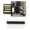
1 | Digispark Kickstarter | 5V | [3] | ||
|
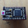
1 | Arduino Pro Micro | 5V / 16MHz | ATmega32U4 mit integriertem USB um als Maus oder Tastatur verwendet zu werden |
Microcontroller
| Bild | Name | Gehäuse | Werte | Datenblatt | Pinouts |
|---|---|---|---|---|---|
|
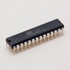
ATmega328P | DIL-28 | 8bit 1.8-5.5 volts | [4] | [5] |
Transistor Bipolar
| Bild | Name | Typ | Werte | Datenblatt |
|---|---|---|---|---|

|
TIP120 | NPN | 60V 5A Darlington | [6] |
Transistor MOSFET
| Bild | n | Name | Channel | Werte | Datenblatt |
|---|---|---|---|---|---|

|
IRLB8721 | N | 30V 60A RDS(on) at 4.5V VGS | [7] | |

|
3 | HY5204W | N | 40V 320A RDS(on) = 1.3mOhm at VGS = 10V TO-247 |
[8] |

|
FQP27P06 | P | -60V -27A | [9] |
Wireless
| Bild | Name | Werte | Datenblatt | Pinouts |
|---|---|---|---|---|

|
nRF24L01 | 1.9 to 3.6V 2Mbps 2.4GHz | [10] | [11] |

|
nRF24L01 + PA + LNA | 1.9 to 3.6V 2Mbps 2.4GHz | [12] | [13] |

|
nRF24L01 mini | 1.9 to 3.6V 2Mbps 2.4GHz | ||

|
ESP8266-01 | 3.3V | [14] | |

|
ESP12e | 3.3V | [15] | |

|
RFM95 LoRa | 3.3V, 868 MHz | [16] | |
|
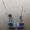
RFM95 LoRa TestBoards | 3.3V, 868 MHz Antenne 8.62 cm Arduino Pro Mini |
DC-DC
| Bild | n | Name | Werte | Input | Output | Amp | Effizienz | Datenblatt |
|---|---|---|---|---|---|---|---|---|
| 1 | LM2596 | CC CV Buck | 7-35v | 1,25-30v | ~79% | |||
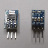
|
2 | AMS1117-3.3 | LDO | max 15 V | 3,3V | 1 A | [17] |
Power
| Bild | n | Name | Werte | Datenblatt |
|---|---|---|---|---|

|
1 | DC-DC Boost | 0,8-3.3V -> 3.3V Ruhestrom 13uA |

|
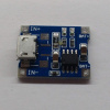
|
2 | TP4056 | Micro USB 5V, 1A LiPo Battery charger |
[18] |
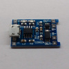
|
2 | TP4056 | Micro USB 5V, 1A LiPo Battery charger With Protection |
[19] |
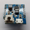
|
1 | Batterie Shield Wemos D1 | ||
|
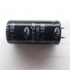
1 2 |
Supercapacitor | 2.7V, 100F 2.7V, 500F |
[20] |
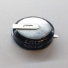
|
1 | Supercapacitor | 5.5V, 4F | |
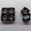
|
12 | 18650 Spacer | ||
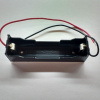
|
1 | 18650 Batteryholder | ||
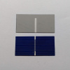
|
12 | Polychristaline Solarzellen | 39 x 19 mm | |
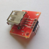
|
1 | USB Weiblich Breakout | ||
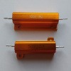
|
2 | High-Power Widerstand Alu-Gehäuse |
1 Ohm 50W und 100W |
Ethernet
| Bild | Name | Werte |
|---|---|---|

|
ENC28j60 | SPI 3.3V |

|
W5500 | 5V |
LED
| Bild | Name | Werte | Hersteller | Datenblatt |
|---|---|---|---|---|

|
LFBML-MW800800-24V-12D167-20 | 24 V, 2700 K + 6000 K, ~1900 lm/m 20 cm Teststreifen |
ledxon | [21] |

|
LFBHL-SW800-24V-6S42-20 | 24 V, 2700 K, ~1250 lm/m 20 cm Teststreifen |
ledxon | [22] |
Motor Driver
| Bild | n | Name | Werte | Link |
|---|---|---|---|---|
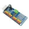
|
1 | PCA9685 Servo Shield Motor Driver | 16 Ch 12-bit PWM | [23] |
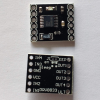
|
1 | DRV8833 Dual Motor Driver | 1.2 A (2 A Max) 2.7 V - 10.8 V |
[24] |
Sensors
| Bild | Name | Werte | Datenblatt |
|---|---|---|---|
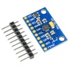
|
MPU-9250 | 9-DOF 3-Axis Accelerometer, Gyro, & Magnetometer | [25] |

|
TinyRTC Real Time Clock | I2C DS1307 AT24C32 | |
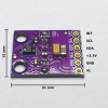
|
APDS-9960 | Digital Proximity, Ambient Light, RGB, and Gesture Sensor | [26] |
Interfacing
| Bild | Name | Werte | Link |
|---|---|---|---|
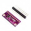
|
ADS1115 Shield | 16-Bit ADC - 4 Channel with Programmable Gain Amplifier | [27] |

|
Adapter-Platinen-SMD | QFP32, SOT23, SOT89, SOT223, SOP28, SOP24, SOP20, SOP16, SOP14, SOP8 |
Sound
| Bild | Name | Werte | Link |
|---|---|---|---|
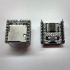
|
DF-Player Mini |