DCEM (Diskussion | Beiträge) |
DCEM (Diskussion | Beiträge) |
||
| (55 dazwischenliegende Versionen von 2 Benutzern werden nicht angezeigt) | |||
| Zeile 1: | Zeile 1: | ||
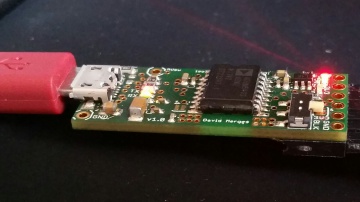
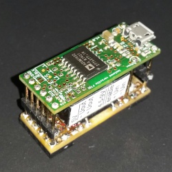
| + | [[Datei:Isolated_FTDI_1.jpg|360px|right|thumb|Isolated versatile FTDI]] | ||
| + | by: DCEM | ||
| + | |||
| + | == Background == | ||
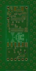
At some point I needed an isolated FTDI. Since I could not find one to buy, I designed one. | At some point I needed an isolated FTDI. Since I could not find one to buy, I designed one. | ||
| − | After talking to some people in the hackerspace with different | + | After talking to some people in the hackerspace with different ideas about the project I designed it so that lots of options are possible with the design. |
You can choose between the ADuM 1402 and the ADuM 5402. The 1402 will need some power on the isolated side while the 5402 can deliver up to 60mA via an internal isolated DC/DC converter. | You can choose between the ADuM 1402 and the ADuM 5402. The 1402 will need some power on the isolated side while the 5402 can deliver up to 60mA via an internal isolated DC/DC converter. | ||
| Zeile 6: | Zeile 10: | ||
I started with the design from sparkfun: [https://www.sparkfun.com/products/9716 FTDI Basic Breakout] which I really liked, thanks for making the design open source, it saved me time. | I started with the design from sparkfun: [https://www.sparkfun.com/products/9716 FTDI Basic Breakout] which I really liked, thanks for making the design open source, it saved me time. | ||
| + | == PINOUT == | ||
| + | <pre> | ||
| + | +----------------------------+ | ||
| + | | FTDI Board -> DTR | | ||
| + | | <- RX | | ||
| + | | U -> TX | | ||
| + | | S VCC | | ||
| + | | B <- CTS | | ||
| + | | GND | | ||
| + | +----------------------------+ | ||
| + | </pre> | ||
| + | |||
| + | == Features == | ||
The features of this FTDI are: | The features of this FTDI are: | ||
* galvanic isolation via ADuM 1402 or ADuM 5402 (that’s what all the fuzz is about :) ) | * galvanic isolation via ADuM 1402 or ADuM 5402 (that’s what all the fuzz is about :) ) | ||
* small (15.1*0.61/38,4*15,5) | * small (15.1*0.61/38,4*15,5) | ||
* Micro-USB-B connector (these are the cables I carry around anyways) | * Micro-USB-B connector (these are the cables I carry around anyways) | ||
| − | * 5V,5V switched, GND and FTDI connections in a 0.1 grid, so you can stack it onto a Universal PCB | + | * 5V,5V switched, GND and FTDI connections in a 0.1 grid, so you can stack it onto a Universal PCB (stack a bigger DC/DC Converter for full 500mA for example) |
| + | |||
The optional features of this FTDI are: | The optional features of this FTDI are: | ||
| Zeile 19: | Zeile 37: | ||
* Instead of PTC-Fuse: Current Limiting Power Switch 500mA (MIC2005A-1YM5 or similar) | * Instead of PTC-Fuse: Current Limiting Power Switch 500mA (MIC2005A-1YM5 or similar) | ||
* USB Bus Powered with Power Switching Configuration (see page 25 of the FT232R datasheet) | * USB Bus Powered with Power Switching Configuration (see page 25 of the FT232R datasheet) | ||
| + | |||
The optional features of this FTDI with the Adum5402 are: | The optional features of this FTDI with the Adum5402 are: | ||
| Zeile 25: | Zeile 44: | ||
* Current Limiting Power Switch 50mA to protect the ADuM5402 (MIC2090-1YM5 or similar) | * Current Limiting Power Switch 50mA to protect the ADuM5402 (MIC2090-1YM5 or similar) | ||
| − | + | == Design Files == | |
| + | Circuit: [[Datei:isolated versatile FTDI.pdf]] | ||
| + | Eagle files: [[Datei:isolated versatile FTDI.zip]] | ||
| − | + | == Finished PCBs == | |
| + | <gallery caption="Soldered PCBs"> | ||
| + | Datei:Isolated_FTDI_1.jpg|FTDI adapter in action | ||
| + | Datei:Isolated_FTDI_2.jpg|Back side FTDI adapter | ||
| + | Datei:Isolated_FTDI_3.jpg|Front FTDI adapter extended version | ||
| + | Datei:Isolated_FTDI_4.jpg|Front FTDI adapter simple version | ||
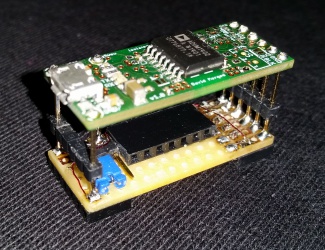
| + | Datei:Isolated_FTDI_5.jpg|Stacking FTDI adapter with DC/DC converter | ||
| + | </gallery> | ||
| + | |||
| + | |||
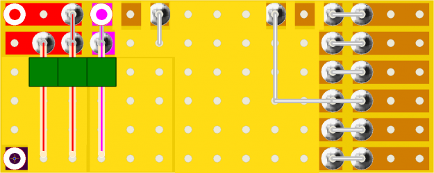
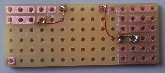
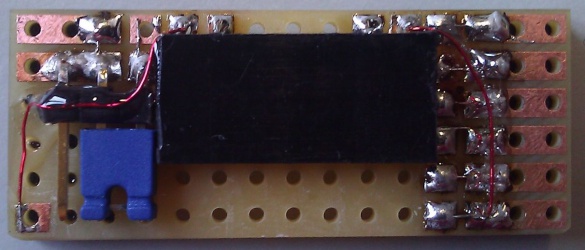
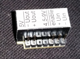
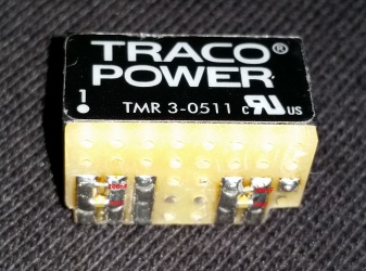
| + | == Stacking FTDI adapter with DC/DC converter (500mA) == | ||
| + | Traco Power: | ||
| + | |||
| + | TMR 3-0511 5V | ||
| + | |||
| + | TMR 3-0510 3V3 | ||
| + | |||
| + | |||
| + | [[Datei:Isolated_FTDI_DC-DC-Stack-Plan.png|x250px|]] | ||
| + | |||
| + | [[Datei:Isolated_FTDI_DC-DC-Stack-Board_1.jpg|x250px|]] | ||
| + | [[Datei:Isolated_FTDI_DC-DC-Stack-Board_2.jpg|x250px|]] | ||
| + | |||
| + | [[Datei:Isolated_FTDI_DC-DC-Board_1.jpg|x250px|]] | ||
| + | [[Datei:Isolated_FTDI_DC-DC-Board_2.jpg|x250px|]] | ||
| + | |||
| + | [[Datei:Isolated_FTDI_DC-DC-Stack-without.jpg|x250px|]] | ||
| + | [[Datei:Isolated_FTDI_5.jpg|x250px|]] | ||
| + | |||
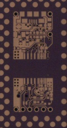
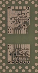
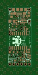
| + | == PCBs == | ||
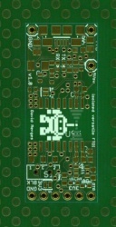
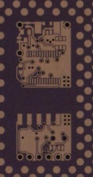
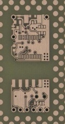
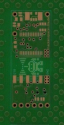
First PCBs are ordered and we will solder them in a few weeks. | First PCBs are ordered and we will solder them in a few weeks. | ||
| + | Progress: | ||
| + | |||
| + | [[Datei:Progress isolated versatile FTDI TOP 1.jpg|x250px|]] | ||
| + | [[Datei:Progress isolated versatile FTDI TOP 2.jpg|x250px|]] | ||
| + | [[Datei:Progress isolated versatile FTDI TOP 3.jpg|x250px|]] | ||
| + | [[Datei:Progress isolated versatile FTDI TOP 4.jpg|x250px|]] | ||
| + | [[Datei:Progress isolated versatile FTDI TOP 5.jpg|x250px|]] | ||
| + | |||
| + | [[Datei:Progress isolated versatile FTDI BOTTOM 1.jpg|x250px|]] | ||
| + | [[Datei:Progress isolated versatile FTDI BOTTOM 2.jpg|x250px|]] | ||
| + | [[Datei:Progress isolated versatile FTDI BOTTOM 3.jpg|x250px|]] | ||
| + | [[Datei:Progress isolated versatile FTDI BOTTOM 4.jpg|x250px|]] | ||
| + | [[Datei:Progress isolated versatile FTDI BOTTOM 5.jpg|x250px|]] | ||
| + | |||
| + | |||
| + | |||
| + | == Bill of Materials / Jumper Configuration == | ||
| + | === basic === | ||
| + | * '''solder SJ_VE1''' | ||
| + | |||
| + | {|class="wikitable" style="text-align: left; color: #333; padding:12px; vertical-align:top; " | ||
| + | !Quantity!!Part Name!!Value/Part No!!Size | ||
| + | |- | ||
| + | |1|| ||PCB|| | ||
| + | |- | ||
| + | |1||USB Connector MICRO B||ZX62-B-5PA(11)|| | ||
| + | |- | ||
| + | |1||.1 inch Header 6P|| || | ||
| + | |- | ||
| + | |1|| ||ADuM1402 || | ||
| + | |- | ||
| + | |1||U1||FT232RL|| | ||
| + | |- | ||
| + | |4||C2, C3, C4, C6||100nF||0402 | ||
| + | |- | ||
| + | |1||C9||10µF||1206 | ||
| + | |- | ||
| + | |} | ||
| + | |||
| + | === RX/TX LED for serial traffic indication === | ||
| + | {|class="wikitable" style="text-align: left; color: #333; padding:12px; vertical-align:top; " | ||
| + | !Quantity!!Part Name!!Value/Part No!!Size | ||
| + | |- | ||
| + | |1||LED_TX||LED red (2mA)||0603 | ||
| + | |- | ||
| + | |1||LED_RX||LED green (2mA)||0603 | ||
| + | |- | ||
| + | |2||R1, R2||2K2||0603 | ||
| + | |- | ||
| + | |} | ||
| + | |||
| + | === Shield connection via RC element === | ||
| + | {|class="wikitable" style="text-align: left; color: #333; padding:12px; vertical-align:top; " | ||
| + | !Quantity!!Part Name!!Value/Part No!!Size | ||
| + | |- | ||
| + | |1||R3||330R||0805 | ||
| + | |- | ||
| + | |1||C7||220nF X7R||0805 | ||
| + | |- | ||
| + | |} | ||
| + | |||
| + | === ESD Protection (USB) === | ||
| + | {|class="wikitable" style="text-align: left; color: #333; padding:12px; vertical-align:top; " | ||
| + | !Quantity!!Part Name!!Value/Part No!!Size | ||
| + | |- | ||
| + | |1|| ||SRV05|| | ||
| + | |- | ||
| + | |} | ||
| + | |||
| + | === PTC-Fuse 500mA (USB) === | ||
| + | * '''cut SJ_VBUS''' | ||
| + | {|class="wikitable" style="text-align: left; color: #333; padding:12px; vertical-align:top; " | ||
| + | !Quantity!!Part Name!!Value/Part No!!Size | ||
| + | |- | ||
| + | |1||PTC_FUSE||PTC-Fuse 500mA||1812 | ||
| + | |- | ||
| + | |} | ||
| + | |||
| + | === Current Limiting Power 500mA (instead of PTC-Fuse) === | ||
| + | * '''cut SJ_VBUS''' | ||
| + | {|class="wikitable" style="text-align: left; color: #333; padding:12px; vertical-align:top; " | ||
| + | !Quantity!!Part Name!!Value/Part No!!Size | ||
| + | |- | ||
| + | |1|| ||MIC2005A-1YM5|| | ||
| + | |- | ||
| + | |1||C5||1µF||0603 | ||
| + | |- | ||
| + | |1||C9||100µF||1206 | ||
| + | |- | ||
| + | |} | ||
| + | |||
| + | === Power Switching Configuration === | ||
| + | * '''cut SJ_5V_SW''' | ||
| + | {|class="wikitable" style="text-align: left; color: #333; padding:12px; vertical-align:top; " | ||
| + | !Quantity!!Part Name!!Value/Part No!!Size | ||
| + | |- | ||
| + | |1||Q1||IRLML2244TRPBB|| | ||
| + | |- | ||
| + | |1||R6||10K||0603 | ||
| + | |- | ||
| + | |1||R7||1K||0603 | ||
| + | |- | ||
| + | |2||C1, C8||100nF||0402 | ||
| + | |- | ||
| + | |} | ||
| + | |||
| + | === ADuM5402 === | ||
| + | {|class="wikitable" style="text-align: left; color: #333; padding:12px; vertical-align:top; " | ||
| + | !Quantity!!Part Name!!Value/Part No!!Size | ||
| + | |- | ||
| + | |1|| ||ADuM5402|| | ||
| + | |- | ||
| + | |2||C10, C11||10µF||0603 | ||
| + | |- | ||
| + | |} | ||
| + | |||
| + | ==== Switch for output voltage selection (3V3/5V) ==== | ||
| + | * '''cut SJ_V+_5V''' | ||
| + | {|class="wikitable" style="text-align: left; color: #333; padding:12px; vertical-align:top; " | ||
| + | !Quantity!!Part Name!!Value/Part No!!Size | ||
| + | |- | ||
| + | |1||S1||SSK-1202|| | ||
| + | |- | ||
| + | |} | ||
| + | |||
| + | ==== LEDs for voltage selection feedback ==== | ||
| + | {|class="wikitable" style="text-align: left; color: #333; padding:12px; vertical-align:top; " | ||
| + | !Quantity!!Part Name!!Value/Part No!!Size | ||
| + | |- | ||
| + | |1||LED_3V3||LED orange (2mA)||0603 | ||
| + | |- | ||
| + | |1||LED_5V||LED red (2mA)||0603 | ||
| + | |- | ||
| + | |1||R4||2K2||0603 | ||
| + | |- | ||
| + | |1||R5||1K||0603 | ||
| + | |- | ||
| + | |} | ||
| + | |||
| + | ==== Current Limiting Power Switch 50mA to protect the ADuM5402 ==== | ||
| + | * '''cut SJ_V+''' | ||
| + | {|class="wikitable" style="text-align: left; color: #333; padding:12px; vertical-align:top; " | ||
| + | !Quantity!!Part Name!!Value/Part No!!Size | ||
| + | |- | ||
| + | |1|| ||MIC2090-1YM5|| | ||
| + | |- | ||
| + | |1||C12||10µF||0603 | ||
| + | |- | ||
| + | |} | ||
| + | |||
| + | == License == | ||
| + | |||
| + | Licensing CC v3.0 Share-Alike (http://creativecommons.org/licenses/by-sa/3.0/) | ||
| + | |||
| + | [[Kategorie:Projekte]] | ||
Inhaltsverzeichnis
-
-
Background
-
PINOUT
-
Features
-
Design Files
-
Finished PCBs
-
Stacking FTDI adapter with DC/DC converter (500mA)
-
PCBs
- Bill of Materials / Jumper Configuration
-
License
Aktuelle Version vom 26. März 2015, 14:02 Uhr
Background
At some point I needed an isolated FTDI. Since I could not find one to buy, I designed one. After talking to some people in the hackerspace with different ideas about the project I designed it so that lots of options are possible with the design.
You can choose between the ADuM 1402 and the ADuM 5402. The 1402 will need some power on the isolated side while the 5402 can deliver up to 60mA via an internal isolated DC/DC converter.
I started with the design from sparkfun: FTDI Basic Breakout which I really liked, thanks for making the design open source, it saved me time.
PINOUT
+----------------------------+
|  FTDI Board         -> DTR |
|                     <- RX  |
| U                   -> TX  |
| S                      VCC |
| B                   <- CTS |
|                        GND |
+----------------------------+
Features
The features of this FTDI are:
- galvanic isolation via ADuM 1402 or ADuM 5402 (that’s what all the fuzz is about :) )
- small (15.1*0.61/38,4*15,5)
- Micro-USB-B connector (these are the cables I carry around anyways)
- 5V,5V switched, GND and FTDI connections in a 0.1 grid, so you can stack it onto a Universal PCB (stack a bigger DC/DC Converter for full 500mA for example)
The optional features of this FTDI are:
- RX/TX LED for serial traffic indication (I always use low current LEDs to save power)
- Shield connection via RC element
- ESD Protection (USB) via SRV05 or Würth 82400102
- PTC-Fuse 500mA (USB)
- Instead of PTC-Fuse: Current Limiting Power Switch 500mA (MIC2005A-1YM5 or similar)
- USB Bus Powered with Power Switching Configuration (see page 25 of the FT232R datasheet)
The optional features of this FTDI with the Adum5402 are:
- Switch for output voltage selection (3.3V / 5V)
- LEDs for voltage selection feedback (same colours as the cables in your ATX power supply ;) )
- Current Limiting Power Switch 50mA to protect the ADuM5402 (MIC2090-1YM5 or similar)
Design Files
Circuit: Datei:Isolated versatile FTDI.pdf
Eagle files: Datei:Isolated versatile FTDI.zip
Finished PCBs
- Soldered PCBs
Stacking FTDI adapter with DC/DC converter (500mA)
PCBs
Bill of Materials / Jumper Configuration
basic
- solder SJ_VE1
| Quantity | Part Name | Value/Part No | Size |
|---|---|---|---|
| 1 | PCB | ||
| 1 | USB Connector MICRO B | ZX62-B-5PA(11) | |
| 1 | .1 inch Header 6P | ||
| 1 | ADuM1402 | ||
| 1 | U1 | FT232RL | |
| 4 | C2, C3, C4, C6 | 100nF | 0402 |
| 1 | C9 | 10µF | 1206 |
RX/TX LED for serial traffic indication
| Quantity | Part Name | Value/Part No | Size |
|---|---|---|---|
| 1 | LED_TX | LED red (2mA) | 0603 |
| 1 | LED_RX | LED green (2mA) | 0603 |
| 2 | R1, R2 | 2K2 | 0603 |
Shield connection via RC element
| Quantity | Part Name | Value/Part No | Size |
|---|---|---|---|
| 1 | R3 | 330R | 0805 |
| 1 | C7 | 220nF X7R | 0805 |
ESD Protection (USB)
| Quantity | Part Name | Value/Part No | Size |
|---|---|---|---|
| 1 | SRV05 |
PTC-Fuse 500mA (USB)
- cut SJ_VBUS
| Quantity | Part Name | Value/Part No | Size |
|---|---|---|---|
| 1 | PTC_FUSE | PTC-Fuse 500mA | 1812 |
Current Limiting Power 500mA (instead of PTC-Fuse)
- cut SJ_VBUS
| Quantity | Part Name | Value/Part No | Size |
|---|---|---|---|
| 1 | MIC2005A-1YM5 | ||
| 1 | C5 | 1µF | 0603 |
| 1 | C9 | 100µF | 1206 |
Power Switching Configuration
- cut SJ_5V_SW
| Quantity | Part Name | Value/Part No | Size |
|---|---|---|---|
| 1 | Q1 | IRLML2244TRPBB | |
| 1 | R6 | 10K | 0603 |
| 1 | R7 | 1K | 0603 |
| 2 | C1, C8 | 100nF | 0402 |
ADuM5402
| Quantity | Part Name | Value/Part No | Size |
|---|---|---|---|
| 1 | ADuM5402 | ||
| 2 | C10, C11 | 10µF | 0603 |
Switch for output voltage selection (3V3/5V)
- cut SJ_V+_5V
| Quantity | Part Name | Value/Part No | Size |
|---|---|---|---|
| 1 | S1 | SSK-1202 |
LEDs for voltage selection feedback
| Quantity | Part Name | Value/Part No | Size |
|---|---|---|---|
| 1 | LED_3V3 | LED orange (2mA) | 0603 |
| 1 | LED_5V | LED red (2mA) | 0603 |
| 1 | R4 | 2K2 | 0603 |
| 1 | R5 | 1K | 0603 |
Current Limiting Power Switch 50mA to protect the ADuM5402
- cut SJ_V+
| Quantity | Part Name | Value/Part No | Size |
|---|---|---|---|
| 1 | MIC2090-1YM5 | ||
| 1 | C12 | 10µF | 0603 |
License
Licensing CC v3.0 Share-Alike (http://creativecommons.org/licenses/by-sa/3.0/)
