Ancient Board: Unterschied zwischen den Versionen
(Die Seite wurde neu angelegt: „The goal of this project is to build something that resembles the optics of a certain type of sci-fi device which controls something by putting transparent pla…“) |
(Add PCB photos) |
||
| (Eine dazwischenliegende Version desselben Benutzers wird nicht angezeigt) | |||
| Zeile 16: | Zeile 16: | ||
The visible casing and the plates are laser-cut acrylic plates. They can be engraved as suitable. | The visible casing and the plates are laser-cut acrylic plates. They can be engraved as suitable. | ||
The casing is mounted onto a 3D-printed backplane, which also holds multiple switches. The switches are pressed by protrusions of the inserts (which of course have 135 degree angles!). The slits on the side have a backside made of diffuse acrylic with LEDs mounted behind them to allow illumination of the inserts. | The casing is mounted onto a 3D-printed backplane, which also holds multiple switches. The switches are pressed by protrusions of the inserts (which of course have 135 degree angles!). The slits on the side have a backside made of diffuse acrylic with LEDs mounted behind them to allow illumination of the inserts. | ||
| + | |||
| + | The SVGs for lasercutting are generated "by hand" in python. | ||
| + | The 3D-printed base is generated using MuSCAD[https://pypi.org/project/muscad/] and OpenSCAD[https://openscad.org/]. | ||
| + | |||
| + | <gallery widths="400px" heights="300px"> | ||
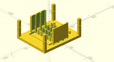
| + | Datei:Ancient_board_base.png|3D printed base | ||
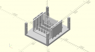
| + | Datei:iter2.png|with insert and translucent side walls | ||
| + | Datei:iter3.png|the translucent side wall is covered by a black front plate with cutouts for the inserts | ||
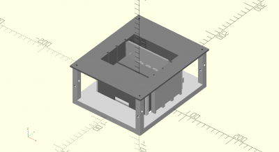
| + | Datei:iter4.png|plates are clipped in horizontally and serve as the bottom of the pocket | ||
| + | Datei:iter5.png|the pocket is closed with plates. cutouts at the bottom allow exit of cables for the switches | ||
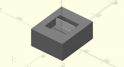
| + | Datei:iter6.png|the whole box is covered with a top plate | ||
| + | Datei:iter7.png|all plates on the side are fixed by screws | ||
| + | </gallery> | ||
==== Electronics ==== | ==== Electronics ==== | ||
| Zeile 21: | Zeile 34: | ||
The system is controlled by an ESP32 running ESP-IDF and FreeRTOS. | The system is controlled by an ESP32 running ESP-IDF and FreeRTOS. | ||
The switches are handled by I2C port expanders. The LED strips are controlled by WS2812 chips. | The switches are handled by I2C port expanders. The LED strips are controlled by WS2812 chips. | ||
| + | |||
| + | <gallery widths="400px" heights="300px"> | ||
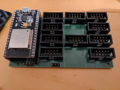
| + | Datei:IMG_20230416_023446_267.jpg|Bottom side with port expanders and logos | ||
| + | Datei:IMG_20230416_023438_465.jpg|Top side with ESP32 and connectors for LEDs and Switches | ||
| + | </gallery> | ||
| + | |||
| + | I'm particularly proud of this because this PCB was a "first" in multiple ways | ||
| + | * It was my first PCB made with '''LibrePCB'''[https://librepcb.org/] (that actually works). If you want do create PCBs with an open source tool and found Eagle much more usable than KiCad, you should check it out. | ||
| + | * It's my first 4-layer PCB. 2 Layers would probably have been sufficient if I spent more time on optimizing the design. But I wanted to try out making a 4-layer PCB anyway. | ||
| + | * It's the first time I soldered TSSOP packages. They are a PITA if you are as motorically incompetent as I am. | ||
Aktuelle Version vom 30. April 2023, 02:42 Uhr
The goal of this project is to build something that resembles the optics of a certain type of sci-fi device which controls something by putting transparent plates at specific places. Examples include the Ancient control crystals in Stargate (which gave the project its name) and control plates in The Expanse.
Important features are:
- transparent plates
- a holder with slits to insert the plates
- *lots* of 135 degree angles (because sci-fi!)
- illumination of the plates
- inserting the plates triggers some feature (what exactly, I don't care) -> it will just publish which plate is inserted via MQTT, and you can connect whatever you want to that
- proper security: Full (client+server) certificate-based TLS authentication+encryption
- configurable in the number of slots, size etc.
Design overview
Construction
The visible casing and the plates are laser-cut acrylic plates. They can be engraved as suitable. The casing is mounted onto a 3D-printed backplane, which also holds multiple switches. The switches are pressed by protrusions of the inserts (which of course have 135 degree angles!). The slits on the side have a backside made of diffuse acrylic with LEDs mounted behind them to allow illumination of the inserts.
The SVGs for lasercutting are generated "by hand" in python. The 3D-printed base is generated using MuSCAD[1] and OpenSCAD[2].
Electronics
The system is controlled by an ESP32 running ESP-IDF and FreeRTOS. The switches are handled by I2C port expanders. The LED strips are controlled by WS2812 chips.
I'm particularly proud of this because this PCB was a "first" in multiple ways
- It was my first PCB made with LibrePCB[3] (that actually works). If you want do create PCBs with an open source tool and found Eagle much more usable than KiCad, you should check it out.
- It's my first 4-layer PCB. 2 Layers would probably have been sufficient if I spent more time on optimizing the design. But I wanted to try out making a 4-layer PCB anyway.
- It's the first time I soldered TSSOP packages. They are a PITA if you are as motorically incompetent as I am.
